Michael (Mick) Connor – Survey Manager at Fulton Hogan – will chat with me on 31st October at 1pm about his team’s use of 12d Model with 12d View (and 12d Synergy). This webinar will be based on a presentation Mick delivered at our 12d Technical Forum in July.
He’ll take us through their journey, and what they encountered on a recent important project – Sydney’s B-Line, which has revolutionised bus travel along the Northern Beaches and Lower North Shore into the northern end of the CBD.
Some of the challenges they encountered on this project included narrow corridors, especially through Neutral Bay and Cremorne, where roads are congested with utilities.
The Fulton Hogan team worked through the night most nights to minimise disruption to users of the existing network until the new one could be launched.
Mick found that the enormous project was detracting from his day-to-day work, and he needed to find a better way to do things. Enter 12d Viewer.
Using this innovation in 12d Model, Mick’s team saw time, cost, and quality benefits, leading to greater empowerment for the engineers involved in the project – it allowed them ownership and accountability, and in turn this allowed Mick to achieve more with his days because he no longer needed to oversee other processes as much.
To hear more about how this was achieved, register to attend our free Industry Solutions Webinar at 1pm (Sydney time) on Wednesday, 31st October, 2018.
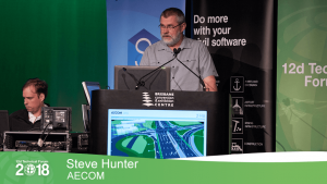
Steve Hunter of AECOM spoke to our 2018 Technical Forum delegates in July about civil object creation in 12d Model software.
Steve said that at the time of the 2016 12d event, most of the designers he was working with had come to grips with workflows and mechanisms to expand their modelling of civil infrastructure with the solid modelling realms of trimesh pavements, plus linear elements such as kerbs and barrier systems. He said they were already reasonably proficient at reading in structural models, and two years later the focus on the digital engineering modelling effort has grown even more intense, with seemingly endless demands to expand the content and depth of 3D models. All this extra output has needed to come without taking its toll on the design effort put in to the generation of end products. The critical word in that last sentence is ‘design’, and it goes a long way to explain the major difference between the process that goes into developing a traditional Building Information Model (BIM) and a modern Digital Civil Engineering Model. Even the difference between the terms ‘Structural Drafter’ and ‘Civil Designer’ gives additional clues as to this difference.
Virtually all the workflows and driving forces behind generating a structural BIM revolve around progressively bolting on more and more detail as the design evolves, with nearly all the detailed embellishments being edited in a virtually static framework. In a civil or linear engineering design – the ‘BIM PowerPoint’ – there is never any guarantee that even the most detailed object is in the final location, or that the number of objects won’t change as designs are optimised to give clients the most cost-effective, safe and practical design; invariably through a process of intensive duration that can even continue into detailed design at times.
In Steve’s opinion, a single majestic pass for a civil engineering design progressively adding on more and more detail to the original concept is likely to lead to delivering a detailed but non-optimised solution. A civil engineering design is a dynamic process, and every detail added to models must be flexible and self-healing, adapting to the many ongoing design changes brought about by the optimisation process to prevent modelling errors. Designers should not allow themselves to be ‘painted into a corner’, unwilling to make major improvements or updates to alignments and designs because it’s just too hard to make any manual changes that result.
To Steve, the term ‘BIM’ has come to represent the effort to shoehorn into a civil engineering model a system designed around a building or structural framework. A classic example of this is the mindset of pretending a road is just a really, really tall building with cars driving on it, and that the floors are regularly shaped segments along the road. Of course, roads are notoriously uncooperative and have awkward stuff in them like interchanges, which pushes the building analogy to its limit!
Steve felt it was important at this juncture to highlight the main purposes of a federated linear engineering model. By far the most important is that of space-proofing – eradicating clashes between objects created by the various design teams that contribute to the final design; this has always been the cause of many last-minute frantic design changes out on site when most of these clashes were finally discovered.
Of course, to run this space-proofing or clash detection process, which is not always a formal reporting process as it also includes the simple but always effective ‘eyeballing’ process, you need to have all these objects created to the level of detail appropriate to their use in the digital engineering model. This leads to the debate about what constitutes an appropriate level of detail for a particular object. For instance, when modelling the top of an access chamber, does adding the surface textures really add to the value of the space-proofing process? As you continue to work your way through the list of details that don’t contribute to the space-proofing function of this object, you eventually get something that takes up the rim of the riser and the lid, and which is located where the access point will be relative to the part configuration as this may impact on surface features.
One of the other important uses of civil objects is as placeholders for additional information or metadata about the object, meaning that unnecessary detail does not need to be crammed into civil objects, particularly when most of these are actually standard objects, and this additional information can be provided by simply referencing the documents containing this additional detail. An example of unnecessary detail is including something like a physical grate in a model of civil objects. This level of detail bloats model data size with little real benefit to the primary reasons for modelling these objects in the first place. A solid object taking up the space occupied by the grate with metadata attached to it has exactly the same value without the data footprint.
Humans are primarily visual creatures, Steve maintains, and we are programmed to think that the level of pleasing, superficial visual detail is directly comparable to something’s true value in this world. In the 12d world, a classic example you often see of this is something simple like non-textured vs textured TINs – it looks pretty and visually appealing, but the true value of the 3D model in a perspective view is shown in a simpler but correspondingly more valuable non-rendered way when design abnormalities are visible and can be identified and rectified.
The 3D models produced by Steve’s team are engineering models, not visualisation models, and this is particularly the case when trying to inject realism into models to make them theoretically better, while actually reducing their true engineering value. There’s an ongoing debate about how to model hybrid linear objects such as guardrails where they can use the realistic looking 12d Model extruders to show the posts and rail for guardrails, and even use these extrudes for sight distance checks.
AECOM’s guardrail snippet produces a trimesh region representing the space above ground for sight distance checking, and another below ground that the guardrail installation will occupy for clash detection. Their civil designers keep challenging the engineering value of modelling individual posts, and repeatedly point out that it can actually be misleading to apply interval-based posts based on the extents of the strings designed to represent the guardrail. Even if end treatments are excluded and simply paced out in two-metre steps from the start of the guardrail string, this process starts to unravel where the guardrail passes from one MTF function to another, resulting in a new string and a reset in the post placing. This means that the posts are potentially in the wrong location and false positives could result when running clash detection reports. False negatives that flag further investigation are vastly more acceptable than false positives, which can mask potential problems.
Humans often have the tendency to jump to the conclusion that something which looks more detailed is automatically more accurate. There are examples of fence posts being shown in great detail but in purely interval-based locations; they’re not representative of where they’ll actually be built. Treating fences and noise walls with the same logic as guardrails, the AECOM team runs a custom extrude along a super string representing the fence location, generating a model of the zone where the fence post may be, and addressing the potential clashes more closely when they are identified. Their current challenge in how they model isolated civil objects in a practical manner is doing so in a fashion which does not require a ‘doctorate in macro programming’, therefore limiting it to a select few. The process also needs to be immune to inevitable design changes as the engineering model is optimised and amended throughout its design life cycle. Civil objects they need to include in their digital engineering model originate either inside or outside 12d. Inside 12d they have 3D features such as electrical objects and survey models; outside 12d they often have 2D features (generated by specialists in other packages) – e.g. signs and line marking or street lighting and traffic signal layouts. It can be pretty alarming that objects which appear insignificant on a 2D drawing actually occupy a large amount of 3D space through which they’re trying to thread proposed utilities.
The civil object workflow is not limited to existing and proposed utilities, and can be used for other civil objects such as a very large chunk of concrete that may be needed for anchoring wire rope safety barrier systems. Bearing in mind that the reason they’re creating these civil objects in the first place is primarily for space-proofing, an allowance needs to be made for such a large block of concrete. What makes this object different from, say, a light post, is firstly that the holding symbol needs to be applied to the end of the model of the wire rope safety barrier string and secondly that the orientation of the holding symbol needs to match that of the string terminal. To achieve this aim, the AECOM team organised to create a custom macro in 12d to achieve this…enter Sam Cech of Tatras Consulting in New Zealand! The resulting wire rope safety barrier snippet produces a result very similar to the guardrail snippet, plus it adds terminal information attributes to the marker string which is then used to place the holding symbol. When the civil object chain is run, the trimesh terminal objects take up space in the federated model for the BIM folk to play with.
Sam’s macro is also used to place civil object holding symbols for other directional objects such as light poles and traffic signals with mast arms. In theory, if the focus is purely on space proofing and clash detection, it is primarily the post and footing that are important; the rest is aesthetics. They do, however, want to make viewing the federated model an intuitive experience to allow for easy visual identification of civil objects, and fortunately setting the orientation to these objects is easy to automate. For the Surveying team at TMR, for instance, the mast arms for traffic signals and light poles are represented by two points running from the lantern to the base of the pole, and by placing a holding symbol at the end of the string and running the civil object chain you get lights that are correctly orientated with a process that’s about the same amount of effort as applying a standard mapping file.
Steve originally thought they’d need a drawing template based civil object chain to run on the drainage PPF plans to evolve their drainage network into what is needed for federated engineering models, but he started investigating the option of drainage trimeshes that are set in the drainage.4d file and – as with the other civil objects shown – it relies on a 3D library of drainage structures to cap off the top of the drainage model chambers, with up to 24 variations needed for each pit style to take into account lintel size, channel width, inflow configuration and orientation relative to the kerb. These have always been defined for hydraulic reasons but now also need to take into account the kerb type to include the kerb transitions in the trimesh (and ultimately in the federated model). The top structure of the gully pits and access chambers orientate themselves in the same way as the drainage plan PPF plots, including automatically adapting to the flow direction so no extra effort is required from the drainage designers because the drainage trimeshes update with a standard set pit details process. Steve was particularly impressed that the drainage trimesh also tilts itself to suit the road grade calculator and the setout string, so the final 3D orientation is actually very close to the real thing.
AECOM’s drainage designers have always modelled the existing drainage network, primarily for hydraulic reasons, but it’s now included in the federated model, and one of the processes designers typically had to do pre-BIM was to separate the drainage model into the kind of categories or states that are referred to in the modelling of utilities, partly because the various states can then be visually identified or even manipulated visually in the federated engineering model. Engineers and ‘BIM folk’ become concerned if they see a drainage structure in the middle of the road on a design, even if it is one that’s flagged for removal, so it may be necessary to temporarily hide objects such as these. You can currently do this in 12d Model by incorporating and identifying the pit and pipe names and filtering for these in the drainage trimesh model – i.e. splitting them into submodels.
The final plan integration of these model drainage structures into AECOM’s models is adapting the road designs to leave gully pit shaped holes in their design surfaces and other trimeshes. Steve ‘tried to be sneaky’ by including a boundary string in the drainage pit trimesh definition which could then potentially be used with a 12d Model 14 trimesh cookie cutter, but unfortunately 12d was too smart for that and ignored it when reading into the drainage trimeshes! His team can, however, adjust their road strings to suit a drainage object with a bunch of fiddly MTF modifiers, tucking these away inside snippets to avoid alarming those poor engineers and BIM designers. It is even possible to create a null string containing the TIN boundary attribute to automatically cut a hole in any TIN the boundary is actually included in.
Enter your details to view the full presentation here.
Aidan Bickhoff – then a Civil Designer with Sunshine Coast Regional Council – speaks of his 2016 work designing a macro in 12d Model software to assist with the Local Government Infrastructure Plan (LGIP), in line with the Sustainable Planning Act (SPA 2009). Customisation using macros is a great way to get the most out of a comprehensive software package like 12d Model.
This undertaking was spurred on by a need to quickly develop multiple intersection concept design options and analyse the practicality and efficiency of these conceptual designs. Aidan’s role at Sunshine Coast Regional Council was to prepare designs for inclusion in the LGIP. The scope of the LGIP for which Aidan’s team was responsible was approximately $270 million between 2016-2031. The team was often called upon to prepare multiple design options – sometimes 15 or more – and multiple iterations of each option were required for each potential project with the LGIP to be submitted to the state government for approval. As the only Civil Designer in the team, it was a very time-consuming process to design all these options, and equally time-consuming for other members of the team to analyse and model the intersections.
It was clear that they were going to be unable to deliver the LGIP for submission to the state government without applying more resources (which wasn’t an option) or missing their deadline (again not an option).
They needed a more efficient design and analysis process…and so, from the fire and flames that is a raging Civil Designer’s desk, the SIDRA-2-12D Bridge was born one Saturday afternoon…and even in its early development phase, the team was able to get some proof-of-concept projects with a few basic intersection components/forms exported from 12d Model into SIDRA, and back again!
The current workflow and method of designing a static concept intersection within AutoCAD was very slow, and it couldn’t be dynamically updated post-optimisations from SIDRA. Furthermore, it was a cumbersome process and required manual translation of design data and variables from paper plans (AutoCAD output) into SIDRA…and vice-versa.
Old Workflow:
o Prepare concept design / intersection layout in AutoCAD
o Plot design as scaled drawing
o Create a new SIDRA Project
o Manually determine the intersection form (T-Intersection, Signals, Roundabout etc.)
o Scale & measure intersection details (Number of lanes, lane lengths, lane width etc.)
o Run SIDRA Analysis
o Optimise the design and re-analysis within SIDRA
o Print or PDF Intersection diagram from SIDRA
o Modify design in AutoCAD
After Aidan’s creation of the 12d Model Macro, ‘SIDRA-2-12D Bridge’, and a few customised intersection components, the team was able to seamlessly transfer the design properties of a Roundabout and Signalised Intersection to SIDRA for analysis, and then import the SIDRA output and re-run a design chain to update the intersection component.
New Workflow:
o Prepare concept design in 12d Model using a Customised Component
o Use the SIDRA-2-12D Bridge to create and pre-populate a SIDRA intersection project
o Run SIDRA Analysis
o Optimise the design and re-analysis within SIDRA
o Import the optimised design into 12D using the SIDRA-2-12D Bridge
o Run chain command to update component
o Reward yourself with some coffee and a donut, because you can actually finish at 5pm today!
Along with the two 12d Macros, one to Import and the other to Export the intersection component data, there were also a few other support files to liaise with the SIDRA .dll libraries and talk to the SIDRA database. From my proof-of-concept tests, Aidan was able to do over a week’s worth of work and refinement of designs in a few hours! Once the macros and translation files were further fine-tuned and matured, even more time savings began, both from a designer perspective and a traffic engineering/analysis perspective.
Where previously the design, analysis and optimisation process took days (often more than a week at a time), by combining the power and flexibility of 12d Components with SIDRA, this can now be done in 4-5 hours!
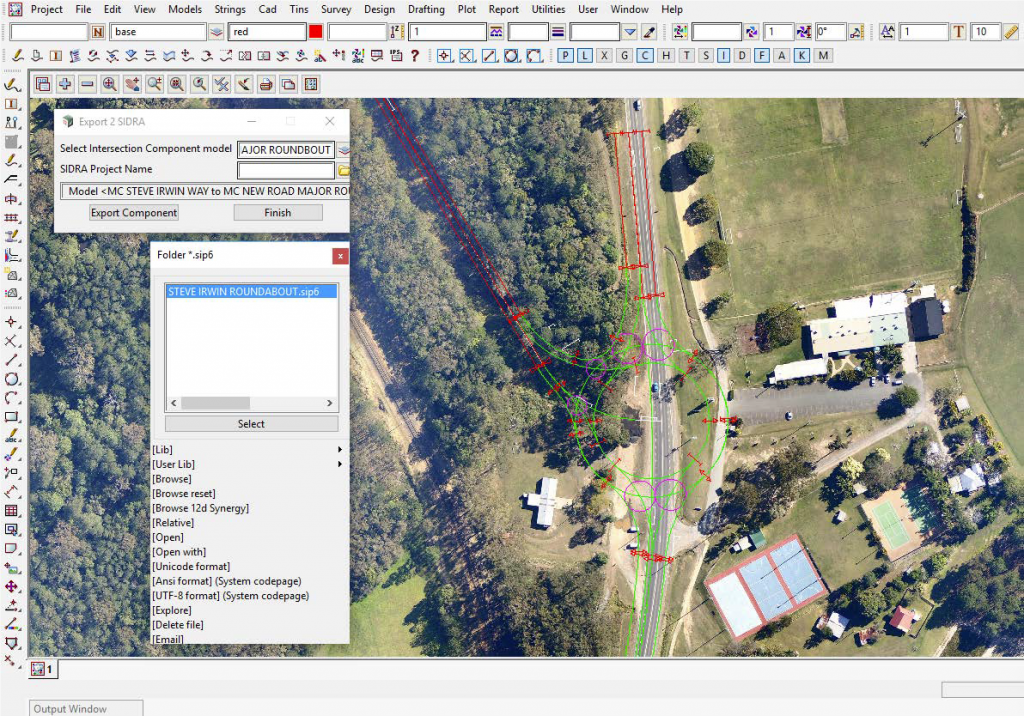
Figure 1: Export the component properties from 12d to SIDRA
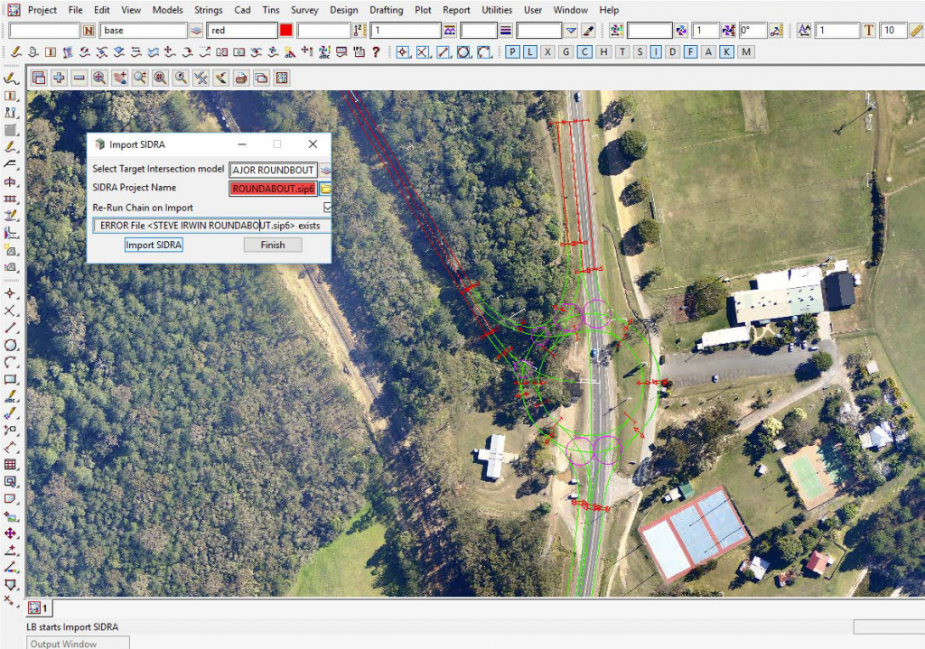
Figure 2: Import optimised design from SIDRA and populate the component and re-run the chain in 12d
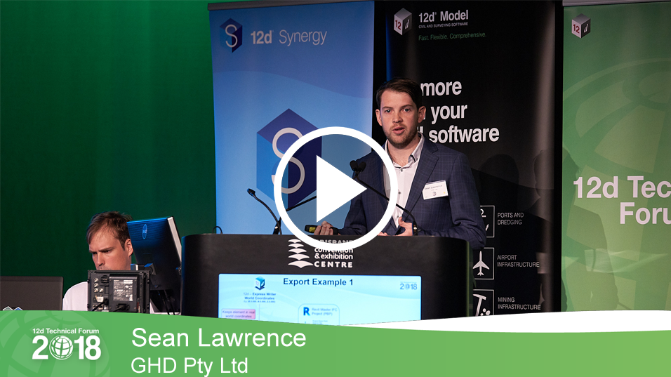
Sean Lawrence of GHD Pty Ltd addressed our 12d Technical Forum delegates in July about his team’s use of 12d Model and Revit. Sean stated that using 12d Model with Industry Foundation Classes (IFCs) and Revit is quite advantageous for all Revit users; using this information allows them to have greater collaboration between the two products.
Previously, in other projects, the challenges they faced involved linking 12d Model drainage network models into Revit (various methods used include 3D CAD, ExDS .xml Generator, an Excel-based generator), 12d TINs into Revit (limited information) and Civil data into Revit (various plugins including Dynamo to try and replicate civil design data such as track slabs for light rail). However, across a major project, replicating 12d data in Dynamo without a dedicated resource can be a lengthy process. These methods often involved long and complicated import processes, and they only had limited information.
Using 12d Model with IFC helped to alleviate some of this. IFCs are the global standard used to describe, share, and exchange construction and facilities management information. As a data format, IFC is neutral and non-proprietary (i.e. not the product of, or favouring, any particular vendor).
GHD’s workflow for using 12d Model with Revit entails exporting an IFC file from 12d Model, editing the IFC file in a text editor, then linking it into Revit. They use the IFC Express Writer within 12d Model to facilitate this process. Once they’ve shifted the 12d Model closer to zero for Revit, they open it with a text editor so as to change the IFCCartesianPoint to 0,0 (the IFCCartesianPoint is the coordinate used by Revit as its placement point). This process will stop the data from being distorted and therefore useable by Revit. This model shift and step of editing the file is not done for other software like Navisworks.
When exporting from 12d Model to Revit, Sean said it’s important to remember to change the IFCCARTESIANPOINT to ((0.0,0.0,0.0)), making sure the origin in the IFC Express Writer Dialogue Box matches the Revit Project base point coordinates, and to ensure the Export Attributes box has been ticked.
Before they bring it into Revit, they set up a few options that allow them to map certain 12d Model elements and IFC classes to an appropriate object inside Revit. They achieve this by setting up a template with a pre-defined project base point which allows them to generate a model in real-world coordinates. They also set an IFC mapping class, which allows them to map 12d elements to the correct Revit categories e.g. pipes that come out on an IFC element assembly to the Pipes category inside Revit, 12d TINs to a Site category inside Revit, and for anything that’s on a building element proxy, they can choose to map this to a generic model or something else.
Linking an IFC file into Revit creates a few extra automatic files (IFC files, Revit files, HTML Log files, and Shared Parameters files, which are used for mapping attribute data from 12d Model a parameter inside Revit). Sean demonstrated aspects of these processes, including handy tips for how to get around some issues that can arise, and how interrogating a model in Revit allows them to see all the different kinds of data that are coming through from attributes in 12d Model. Mapping attributes and checking calculations are correct is essential to this process.
So what is actually generated when we put an IFC into Revit from 12d Model? All the element information comes from the 12d Attributes, but it’s a static model when linking into Revit. By using these programs together, Sean’s team was able to produce an accurate replication of geometry without having to re-model through Dynamo. The colours were driven from 12d Model polygon colour mapping, which was ideal for standardisation. They used a Shaded/Realistic model with Graphics Display Options – Show Edges = “Off” to make polygon triangulation disappear (something Sean was able to demonstrate to the audience in his presentation), and created Linked Views for project consistency.
The string information from 12d Model, according to Sean, was extremely beneficial as an export – they were able to use IFC generated strings for 3D pick line modelling, and to colour strings by filter or category using the parameter information from 12d Model. Strings were used to show edges in 3D views while “Show Edges” was unticked.
In Plan View, some important steps in GHD’s processes included filtering 12d strings to show Control Lines and Road Linemarking, using filters to hide the lower Trimesh models for a cleaner view, and adjusting transparency to view below the surface. They also used shading techniques to get their Linked View plans looking consistent across all projects. In Section View, they filtered for annotation of different elements.
When linking 12d IFCs into Revit, there are automatically generated schedules for each IFC Class mapped, and schedules are generated as a result of the IFC Class to Revit Category Mapping Template. This allows them to check data and use it for their own techniques when writing documentation.
As with the trimeshes from 12d Model, the GHD team is able to use the IFCSite Export function from 12d to generate a Site category family of any TIN. The ability to export an existing SurveyTIN and SuperTin with Linework for use in drawings have also proved invaluable, as having cross-sectional display control, Plan Shaded, Colour Change, contour and linework control, and the ability to change Mapping of Survey export from ‘Generic Models’ to ‘Lines’ Revit category.
Sean also ran through some of the challenges his team faced in using Revit, such as not being able to edit elements when linking IFC files, and not being able to use colour overrides in Plan or 3D, and how upgrading to 12d Model 14 is helping them to overcome some of these issues. In particular, using IFC 4 in 12d Model 14, the team was able to bring data back into 12d. This method keeps file sizes smaller, allowing for more complex design. ‘Splitting data into Entity models’ allowed them to separate all the IFC elements into their individual IFC Class models.
The GHD team was also impressed by their ability to use these processes in their civil documentation without the need to remodel services – it all came directly out in their annotated cross sections, with the help of macros in 12d Model.
Overall, the positive impact of being able to use 12d Model in this way, Sean said, has given GHD the ability to gain accurate and up-to-date information in a variety of areas, to help them produce even better-detailed design jobs for their clients.
Lisa Stewart caught up with Matt Stephens of 12d Victoria recently, for a very popular Training Webinar about ‘Kerb Return and Cul-de-sac Design’. In this information-packed session, attendees learnt how to create basic kerb returns and cul-de-sacs by using the Kret Convert to Computators command within 12d Model. Matt demonstrated two methods for creating a kerb return using a super alignment, then showed how to incorporate kerb returns into a design, including discussions on the Apply MTF Manager, Snippets, and Chains. He also showed two methods of producing cul-de-sacs in 12d Model, including discussion of road widening envelopes.
In addition, we went through some first principles with super alignments (including converting to IPs or Elements), to see what these tools do for the designer so they can be modified to cater for more complex cases.
The Technical Preview Version of 12d Model 14 is already in use by many of our customers on Maintenance who attended this year’s 12d Technical Forum…stay tuned for details of our 2020 event if you want to get in the loop early for 12d Model 15 as these lucky folks have done this time around!
In our recent Training Webinar entitled ‘Downhill Strings (including new V14 features)’, Owen Thornton of 12d Queensland discussed the Downhill Strings option in 12d Model, used for processing Super strings with z-values. The option has been significantly updated for 12d Model 14, and these changes were highlighted as part of a complete demonstration of the option.
In addition, for drainage designers, the interrelationship with the Utility String Editor was discussed, to modify the properties of the overland flow strings created by Downhill Strings.
NEW in 12d Model 14 Downhill Strings has a new look!
Now with standard source-boxes.
Manually drawn strings (across roads, culvert connections, etc) now only need to be drawn once. They can be specified as Extra Input to be processed and joined (but not downhilled).
Vertex data set by Utility String Editor on previous downhill strings, can be saved and re-applied to the new downhill strings.
Much less work to do when designs change and new downhill strings are required.
Owen also talked us through the four new tabs in the Downhill Strings panel.
Downhill Strings also has:
A new toolbar icon on the new Water
A new location on the new and improved Water
The Technical Preview Version of 12d Model 14 is already in use by many of our customers on Maintenance who attended this year’s 12d Technical Forum…stay tuned for details of our 2020 event if you want to get in the loop early for 12d Model 15 as these lucky folks have done this time around!
12d Model 14…as presented at the 12d Technical Forum 2018!
When 12d Solutions Managing Director Dr Lee Gregory set out to write his opening speech for the 2018 Technical Forum, he decided it was time to make something clear…that we can confidently now call 12d Model the world leading Civil BIM solution! In fact, all the different types of data sets in 12d Model that have already been there for full 3D existed long before people started talking about the word ‘BIM’.
All the different attributes we had – String, Vertex, Segment, Model, Project – how many other packages have vertex and segment attributes as well as string attributes?
We actually showed reading and writing IFC data at our events here in 2010 and even earlier…at the time, many people said ‘why would we want to do that’? Now everyone is talking about BIM.
We’ve always been on the cutting edge of what’s needed…because we listen. Another good example is 12d Field – surveyors using 12d Model on tablets out in the field. Everyone is starting to do that now…15 years later.
We want to continue ‘pushing the boundaries’ (as per the 2018 Technical Forum theme) – that’s why we keep asking for user feedback.
Lee then proceeded to explain the 12d Model Release Cycle. In brief, the full release starts with a version C1a (‘C’ means ‘release version’). Then over the next two years, we release subversions C1b, C1c, etc.
Some developments within a sub version are bug fixes and the like, but we also add new options. So we don’t just stop when we first release a version; we keep working on that version for the next two years…e.g. ARR 2016 etc. went into 12d Model 12…also 12d View.
So we never stop – there is continual development over the lifetime of a 12d Model version.
For example, 12d Model 12 C1a was released in October after the 12d Conference 2016…and that was the time we began work on 12d Model 14. But work still progressed on 12d Model 12 C1b, C1c, etc.
12d View is a free 12d Model viewer. It can use existing 12d Model 12 nodes file and dongles. Users on Maintenance simply register to have access to this handy functionality.
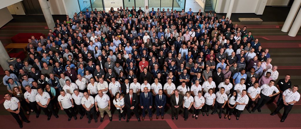
The 12d Technical Forum 2018 is now over, and what a success it was – over 530 attendees! From this very event, users on Maintenance will gain access to the ‘Technical Preview’ version of 12d Model 14. This is the final Beta version – we’d love for you to give us your feedback before we finally release 12d Model 14 in October. If you notice things that are missing or could be done better, feel free to let us know. Once we release, we can’t put anything new into the database, so we like to get everything as complete as possible before then.
Then we’ll start working on 12d Model 15…but we’ll continue adding things to 12d Model 14 until the 2020 Technical Forum.
As previously mentioned, there is no 12d Model 13. We once released a version on Friday 13th and it was a disaster. We’re not generally superstitious, but it seemed sensible not to ‘tempt fate’, as it were!
These features of 12d Model 14 were covered in the ‘What’s Coming’ Webinar earlier this year:
Model tree
Project settings
Civil BIM and IFCs
Combined 12d Field
GDA2020
ARR 2016
Point clouds
Multipage Plots
MTF on steroids
Attribute Manipulator
Setting out BIM
12d View
This is what’s happened since that webinar…
We’ve rearranged the Main Menu – e.g. added BIM menu, Volumes menu, and Water menu; relocated Edit, Drafting, and Window.
We’ve added loads of new features for Water – e.g. the ‘Drainage-Sewer string’ has been replaced by a ‘Water string’, references to ‘pit/manhole/maintenance hole’ now refer to ‘nodes’, references to ‘pipe’ now refer to ‘link’ (this is all better terminology).
You can now display Node HGL and Link HGL in 3D…we’ve added extended nodes and risers for nodes in the Water string, added a Setout diagram for Nodes as well as User defined house connections…and more settings; the list goes on!
Brief notes on ARR 2016, or Australian Rainfall and Runoff 2016 (actually available in 12d Model 12 if you’re on Maintenance):
Events are expressed as Average Exceedance Probability (AEP in %), not Average Recurrence Interval (ARI in years). AEP is approximately the inverse of ARI
For each duration (10min up to 7 days), there are 10 events
Each event is run and the trimmed mean of the 10 storms is calculated (this is the mean excluding outliers e. 2 standard deviations from the mean). The event closest to the trimmed mean is then used as the critical duration
The critical storm is the worst case of all the critical duration events
This is done for every attribute result (catchment flows, pipe flows, pipe velocities, HGLs, volumes…)
Is not Rational method – Dynamic instead. You need the Dynamic Drainage module to use it
10x as long to run but works to standard so necessary
GPU usage for TUFLOW calculations.
Trimeshes were introduced in 12d Model 11 as a generalisation of TINs to represent objects that fold back over themselves. Trimesh usage was expanded in 12d Model 12, and they are now a fundamental part of 12d Model. Trimeshes appeared in many places during the Technical Forum – in User talks, Birds of a Feather sessions, with BIM, Snippets, MTFs, etc.
New trimesh-related features include Face Snap, which allows users to snap on to the face of a trimesh. This, of course, meant a new abbreviation for Fast Snap needed to be found, so it has been renamed to ‘Quick snap’. You can turn off Face snap, and if you’ve got Point snap on it will grab the vertices of a trimesh; if you’ve got Line snap on it will grab the edge.
Other new trimesh-related features include: Creating traffic lights as trimeshes, creating trimeshes from Tunnel Boring Machine (TMB) rings, creating trimeshes for pits, along a string, etc. We’ve also added functionality surrounding MTF for tunnels – inner and outer tunnel walls can be formed as one trimesh, and all the strings can be independently controlled in the MTF.
In fact, there’s so much in the way of examples of further new trimesh-related features that I’m just going to revert to bullet points again now…
Invisible faces so closed for volumes for the inside of the tunnel
Toggle for applying texture mapping in perspective view
Toggle Trimesh wireframe – toggle on/off in an OpenGL view
Drawing density for perspective views – global, view, none
Shade is now turned on by default for a new Perspective View
Joystick – can now go over the top instead of stopping when almost vertical
Move over TIN
Trimesh Editor – add a vertex, delete an edge, pull a whole face out, etc.
12d Trimesh edges can have colours and names – this is very important for setting out
Set trimesh edge info by strings.
We’ve also added a new Settings option for saving various settings for an existing project (Project => Settings) – this replaces a number of files and defaults previously used. There are Named profiles of settings, and a different profile can be selected at any time in a session. Profiles can be duplicated, renamed, deleted, and all saved to a file, and a file of new Profiles can be loaded at any time in a session. You can now turn Super Inquire on/off, and save the Super Inquire style used. Another handy new feature is Autosave screen layout – when this is ticked on and a project is saved, the position and information for most menus and panels on the screen is also saved. The menus and panels will be restored when the project is reopened. We’ve even added the settings for Add/Remove models for Views to Settings, and now have different settings for Search Bar.
In the realm of File I/O, we’ve combined 12da and 12dXML in Reader and Writer, and the ability to write Hexadecimal floating point format to 12da and 12dXML (this is an international IEEE Standard for reading and writing floating point numbers without loss of precision). Real numbers look different but all the other text in the file is readable as normal. You can now tick on panels with anonymous functions, to create (or not create) one, and there are also options to read in KML files, and VISSIM files.
We’ve made additions to the Attribute Manipulator and renamed the menus so you know if a command applies to super strings, TINs, and/or trimeshes. The additions include X, Y, and Z co-ordinates; Element create and modified dates; and linestyles for Segments.
GDA 2020–MGA 2020…stay tuned for a separate piece on this important development!
Plotting in 12d Model has not escaped an overhaul:
Extra Title Block Variables for PPFs
Multiple time formats
New Perspective Plot PPF – image of what is on a Perspective View and/or a 3D PDF
New Section plot PPF (plots the Section View)
New Node Diagram Plot PPF – plot an existing Water Network model
Multipage Plots – MPS – total rewrite.
In 12d Field, we’ve combined Setout and Pickup…more information to come in future blogs on this!
Now, back to that great ‘buzzword’, BIM – Industry Foundation Classes (IFC)…we’re learning more about this every day. Again, though, it’s important to realise that our users have already been ‘doing BIM’ for years. Data in 12d Model has always been in 3D. ADAC for IPWEA – that’s a BIM system…trimeshes all go out to BIM…the list goes on.
IFC is the international standard for BIM; we supported writing to these already, and in 12d Model 14, we’ve added the ability to read IFCs including User Defined Property Sets for attributes. IFC GlobalUID (GUID) can be created and written out, and maintained when read in. For civil works, alignments and TINs are currently being added to the new IFC Standard IFC 4.1, and they are already supported in the IFC Writer.
Another new feature in 12d Model 14 that’s creating quite a stir is Model Tree – a tree name for models, TINs and functions, instead of just having a flat model name. Trees can be viewed as the tree or in a flat form.
We’ve also upgraded our Documentation and added more to the Help menu, which now includes the Reference Manual, Programming Language Manual PDF, What’s New PDF, What’s New Summary HTML, Getting Started for Design, and Getting Started for Surveying manuals.
With our new User Defined Main Menu, you can make up your own main menu up the top, and also define all the sub menus…complete with a button to take you back to the full 12d Model 14 menu if needed (this will be known as the “Sanity button” if you’re talking to Support!).
We could go on…there are over 300 new things in 12d Model 14…but for now, suffice it to say it’s going to be an exciting release and we can’t wait to share it with all of our customers on Maintenance!
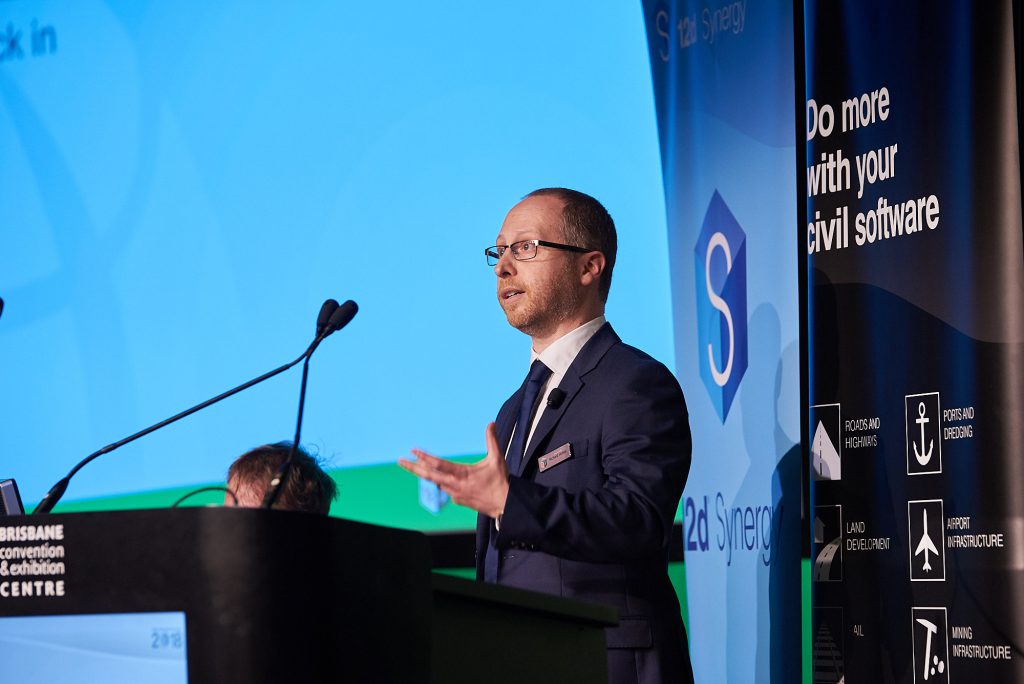
Richard Stoliar – Technical Lead for 12d Synergy – recently spoke to our excited 12d Technical Forum 2018 delegates about the upcoming release of 12d Synergy 4.
Richard Stoliar – Technical Lead, 12d Synergy
Since the release of Version 1.0 in February 2011, a lot has changed in 12d Synergy…we’ve learnt a lot, and responded to feedback, and this new release is going to be a big one. We’ve included over 600 changes, based on user feedback through the Support Portal!
Since 2016, the 12d Synergy user base has grown over 300%…leading to several new staff members required at 12d in various offices.
The main foci for 12d Synergy 4 are:
Speed
As new customers have come on board, we’ve learned a great deal about the different ways in which they structure and access their data – everybody does it just that little bit differently, and we’ve spent a long time analysing that. We’ve worked on making things generally faster as users navigate through the job tree. We’ve looked at faster retrieval of job information and significant optimisation of how we store and analyse files – both these areas have shown marked improvement in Beta Testing. This all leads to less load on infrastructure.
Usability
We had a lot of feedback suggesting that 12d Synergy 3 does a lot of what people need it to do with their files in a managed data environment…but with more mouse clicks than is desirable. We’ve spent a lot of time trying to streamline the interface to give a better experience. This ranges across admin, general day-to-day workflows, adding files, checking items in/out, issuing/transmitting, and 12d Model projects.
Better panel layouts in 12d Synergy 4 help achieve these aims. There’s now a Transfer Progress Bar so you can see how long whole operation will take, not just view timing for individual files. My Recent Items is a handy new shortcut to allow you to quickly access anything you’ve been working on recently.
Column layouts for searches (emails, PDFs, etc.) will also assist users. Workspace Number has been hidden to alleviate the confusion this previously caused in some businesses. It’s easier to on-board users now – administrators can set 12d Synergy up to send out an invitation email to welcome new users and show them how to use the software, add training materials, etc. Users can be grouped, too.
For Issuing and Transmittals there are now more administrative tasks for issued data, like deletion. You’ll be able to issue data to contact lists to avoid repetitive selection of users – you won’t have to pick each user one at a time anymore. Less panels will pop up while you’re doing a transmittal, and with the Transmittal Cover Sheet you can easily display lists of drawings that are in the drawing set, etc.
Naming rules – we’ve always had this option but it’s been improved…for instance, we’ve added capabilities for reduced data entry duplication, zero padding on counters, and multiple counters based on document type.
12d Synergy is a permissions-rich environment. Permissions control who can read/write data, or even who can see that it exists. This can be quite comprehensive – merged across groups, etc. – and in 12d Synergy 3 it could be quite time-consuming to figure out who has access to what. The Permissions Explainer in 12d Synergy 4 helps with this – it’s a simple tool to investigate who has access to what.
Connected Products
We already connected with a number of third-party products in 12d Synergy 3 and earlier; 12d Synergy 4 welcomes Total Synergy and Quick Map.
And of course, the vast majority of our users need to connect 12d Synergy with 12d Model, so we’re constantly looking for ways to improve those processes.
Cached Customisation – you could already put your 12d Model customisations into 12d Synergy 3…but this could make things quite slow. So we reimagined this a bit for v4…and Cached Customisation was born. This means that when you open 12d Model, if it needs to, it will download your User and User Lib in advance, meaning all the subsequent file searching is done locally – it doesn’t need to go back to the server. This works really well with 12d Model because if you change your symbols, toolbars, customisation files, etc., you have to restart the system anyway. There was a lot of work going on before that wasn’t really necessary, and this is significantly faster. It also helps solve the problem with your #Includes within those customisation environments.
We also now have Auto Check Out – previously you were asked the question every time; now you can set it to Auto, as is often the best option for 12d Model projects. Check in and Check out Many, as well as Offline Many (with its options to compress/zip data ahead of transfers), will also speed things up significantly – often users are working on more than one 12d Model project at a time, and it was previously quite slow waiting for each to open individually.
12d Model Project Templates – sometimes you might want to have certain files in your working folder or even in the project directory when you get started on a new 12d Model project and you want to make sure that’s controlled, you want to do it automatically. Now you can have it pop up and ask certain questions – what type of 12d Model project it is, which custom attributes you want, etc.…and based on the answers to those questions, it can pre-create that 12d Model project with everything set up and ready to go.
Administrator definable ignore lists – 12d Model has a tendency to write temporary files in certain instances, and we don’t want those to go back into your source of truth environment. With 12d Synergy 4, you can define which of these gets stored.
We’ve also added functionality for you to roll back or extract versions of single files. History is a big part of what 12d Synergy does, but if you want to, say, roll back five versions of a MTF, you previously had to roll back an entire project (which is often huge)…now you can look for the individual file and just do what you need to.
CAD
CAD is a big feature for 12d Synergy 4. In 12d Synergy 3, we supported AutoCAD and BricsCAD, but it was a little limited. In 12d Synergy 4, we’ve added support for Map 3D, Mechanical, Plant 3D, Civil 3D, etc. 12d Synergy 4 includes support for more reference types – not just DWG. We’ve added support for Sheet Set Manager and for Civil 3D, which includes Data shortcuts, as well as better reference management overall, and support for drawing and title block registers either using Excel or directly using 12d Synergy attributes.
Workflows
The all new Workflow Engine is already causing quite a stir with beta testers. Users have always been able to define attributes in 12d Synergy, much like you can in 12d Model, and attach them to anything in the system. These are really great for decorating items with more information, and they can tell you what stage you’re at in a project, what revision a drawing is on, if a drawing has had a review…but they can’t organise and drive your processes. They can’t tell you if it’s okay to go from one stage to another.
Workflow in 12d Synergy 4 allows you to model your business and day-to-day processes, and perform automatic operations. Its easy point-and-click interface lets you decide what stage you can go to next, and what should happen, e.g. sending an email, locking files, assigning new team members to the workflow.
Spatial and Mapping Capabilities
12d Synergy 3 allowed users to capture addresses and co-ordinates, but it didn’t allow much context for that information. In 12d Synergy 4, you can display maps within the product, using ArcGIS Online. You can then search for jobs using a bounding box, show surrounding jobs within a particular search radius (which is useful for knowing whether there’s historic info in the region you need to look for, or perhaps conflicts of interest, etc.). You can pull in layers from external sources and search for files near your current job (e.g. Dial Before You Dig).
Reports and Gadgets
12d Synergy 4 deploys with lots of reports out of the box, e.g.
Licence usage
User activity
Job details
Changes in files over time
Changes in 12dM projects
You can now also schedule reports – e.g. “For all my active jobs, at the end of every week, I’d like all project managers to get a report.”
Dashboard gadgets provide at-a-glance view of information about your job. These range from basic information to task progress, task status, and who’s done what work lately. They even work through to system administrator issues like the amount of space on disks.
Well now…if all that information doesn’t leave you ‘champing at the bit’ for a peek at 12d Synergy 4, we don’t know what will!
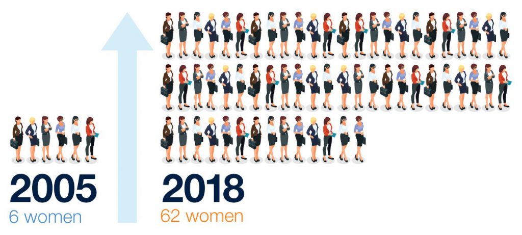
After our 2016 event, I wrote a piece (full article below) about the (albeit slowly) changing face of conference demographics…at that time, the percentage of women in attendance had grown from less than 1% in 2005 to around 5% in 2016…and as I write this today, I’m in the wake of a 2018 event which had a little over 10% female delegates.
Growth of numbers of women attending 12d events – 2005 vs 2018
Now, I won’t pretend I didn’t think about this in the lead-up to the event…I can’t say I didn’t wonder, at least in passing, whether we should be doing more to increase the numbers of women in attendance. Whether we should be offering incentives, creating more ‘content for women’…what’s the answer? Being a woman myself gives me exactly none of these answers.
As the Technical Forum drew nearer, I realised we’d actually been doing a bit of this organically, and I hadn’t really paid attention. In the line-up of presentations, we had more than one woman who’d put her hand up to speak to our eager audiences about a field of expertise. We’d even gone and booked a female guest speaker to try to fill the enormous shoes of Brian Shul, Dr Karl, and Dr Alan Duffy (incidentally, Dr Catherine Ball, the “Dame of Drones”, stepped up to this task with aplomb). At least two of our stand-holders in the exhibition space were women (which only sounds significant when compared with zero, even in 2016). And as things drew even nearer, I discovered that one of the top prizes in our Innovation Awards had been won by a woman, too (congratulations again to Megan Dillon of Mackay Regional Council for her ‘Banishing the Drafting Demon’ win!)…not because anyone felt that this should be the case, but because her entry was so spectacular that the judges just knew it was the one. To my mind at the time, adding too much to this organic gender equality gap-bridging would have felt disingenuous.
In any case, I don’t want to make this a blog entirely about gender (in)equality…there are other interesting demographics from the event I’ve been asked by delegates to share when possible!
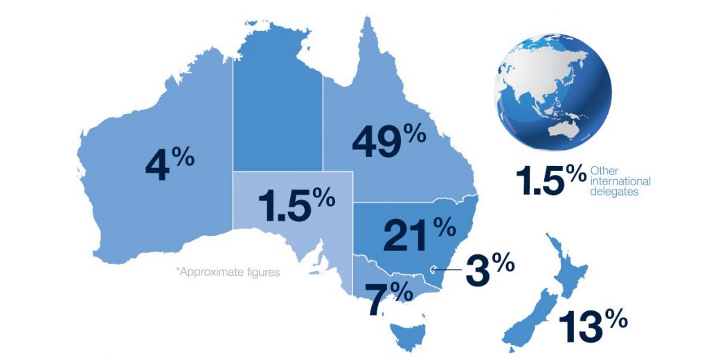
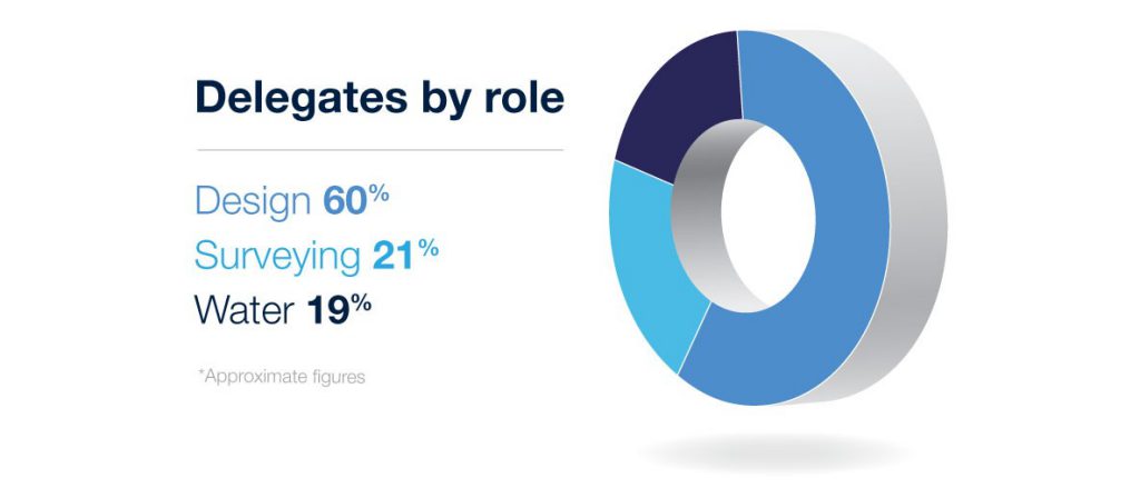
Breakdown of regions – 12d Technical Forum 2018Breakdown of role types – 12d Technical Forum 2018 delegatesGovernment vs Private Sector delegates – 12d Technical Forum 2018
This information is not only interesting, it will be useful for us in planning the many amazing information sessions that will form our 2020 Technical Forum…stay tuned for more details very soon!
–Lisa Stewart
2016 Piece – ‘Observations of Changing Conference Demographics’
Something came to light at our 2016 12d International Conference…we had more women in attendance than ever before. We’ve been holding these Conferences since 2005, and the numbers have been steadily creeping up over that time. We’re not talking life-changing numbers here, by any stretch – we’re still looking at perhaps 5% of delegates being female…but that’s crept up from 1% in 2005, so there’s a definite trend there. It’s noticeable not just anecdotally but statistically, and it was suggested to me that we highlight this somehow. But how?
It’s not that I’m not on board with celebrating bridging a gender gap in industries which really have no reason to be so male-dominated in this day and age. I’m not saying I don’t think it’s great that we’re slowly changing the world and not drawing arbitrary lines down who can participate in which activities. I’m just not sure how to best highlight how great this is without being patronising (I’m not convinced that being a woman myself would lessen the effect of this potential patronisation). Without subjecting these women to something I imagine they deal with almost daily…this concept of ‘othering’. Those moments that they’re reminded that they’re first women, and then engineers (or surveyors, etc.). When will we reach a point when everyone can just be a person with a job instead of a Female Engineer (“Isn’t that interesting?” “How great that a woman can do that!”)? Because why shouldn’t she be able to perform this job, or any, really?
Then again, if we pay no attention to this growing trend, we run the risk of not noticing that we’re progressing – albeit slowly – as a society. These are the indicators of this progress, and we can’t ignore them. But I think we need to just somehow point them out casually and move on, rather than making them a huge focus.
Modelling and attributing services in 12d Model 14…made easy with the addition of new options!
I caught up with 12d Queensland’s Paul Hardwick this week to chat about Survey Utility Modelling as part of our ever-popular Training Webinar Series.
This webinar teaches you how to automate service modelling using tools such as:
Mapfiles
Attribute Manipulator
Service Chamber Many (new to 12d Model 14)
Global Attributes (new to 12d Model 14) – create your own customised list of Attributes!
Translate points by attribute depth (new to 12d Model 14)
Attribute depth validation (new to 12d Model 14)
Paul also talked us through such options as setting wall thickness and floor thickness, Global Close, and Create/Edit Attribute Manipulator File.
As we gear up for the 12d Model 14 release, such exciting ‘sneak peeks’ as this are really where it’s at for us!
The Technical Preview Version of 12d Model 14 is already in use exclusively by many of our customers on Maintenance who attended this year’s 12d Technical Forum…stay tuned for details of our 2020 event if you want to get in the loop early for 12d Model 15 as these lucky folks have done this time around!