Posts

Finding Things Fast in 12d Model

I caught up with Owen Thornton of 12d Queensland to chat about his ideas for ‘Finding Things Fast in 12d Model’.  You can watch the video here:

In this webinar, Owen demonstrates some simple tips and recommendations for improving productivity with 12d Model. The session was mainly intended for less experienced users, though experts might also learn a few new things by watching this. Some of the features being shown were new to 12d Model 12 and have carried through into 12d Model 14.

In 12d Model, the user must effectively manage 12d projects, menus, toolbars, panels, views, functions, models, tins, strings, colours, names…

There’s a variety of tools to make the job easier. Let Owen show you how!

–Lisa Stewart

12d, ESO, and the Northern Beaches Hospital

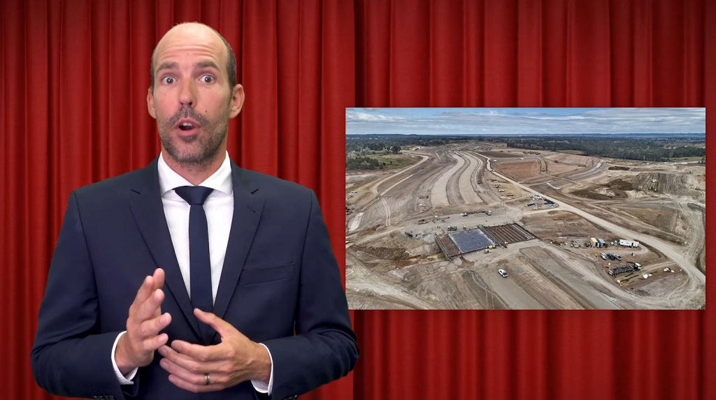
We caught up with Greg Cech from ESO Surveyors, who is currently employed as the Survey Manager on the Northern Beaches Hospital road infrastructure job. Greg has been on that project for two and a half years, and it was going for approximately a year before he started. All of ESO’s work on this project is being done in 12d Model with 12d Field.

As we drove through the project zone, which is just minutes from ESO’s lovely Frenchs Forest office space, we could see their great work in action, and just how much things are taking shape at this point.

Greg confirmed what an exciting project this is to work on, and told us a little about the masses of infrastructure underground – services and such – which of course slowed down the apparent construction for a few months, even though the actual construction was still going on underneath. He said it’s getting to a particularly interesting point from a public perspective as bridges are now being constructed, so people coming past will be able to see the bridges, as well as the slot, which is also starting to be constructed and will be a big visual enhancement in the space. The ‘slot’ is what will come out from Wakehurst Parkway; colloquially it may be known as a ‘tunnel’, but that’s not the technically correct term. Greg told us that it’s actually literally a slot that goes up to about eight metres deep, and the east-west through traffic will run in the slot. Local traffic will run up above it.

During the earlier phases of this project, there were massive disruptions to traffic through the area, but it’s now flowing much better than before. Greg said he hopes it will only get better as they get more and more lanes open up to through traffic.

Warringah Road - ESO
Warringah Road


All in all, a very exciting project, and one we’re proud to say 12d Model and 12d Field are being used for!

Civil BIM and IFCs

12d CEO Dr Lee Gregory addressed our 2018 Technical Forum audience about Civil BIM and Industry Foundation Classes (IFCs) in 12d Model.

View his talk here.

Everyone is talking about BIM, but most people only see bits and pieces of it…a lot of it is jargon, so it’s important to know which parts to pay attention to. Mostly Lee recommends just knowing the basic definitions.

12d Solutions is a member of buildingSMART, which is the international organisation that defines Open BIM or IFCs (Industry Foundation Classes), and a founding member of the Open BIM Alliance (in which, essentially, a number of vendors collaborated, passing IFC data around to see what the problems were), e.g. Qld Govt requires ‘open data’ (no proprietry or undocumented formats) – that’s the future.

12d Solutions is involved in buildingSMART International Conferences/Committees/Expert panels, specifically with the IFC InfraRoom, which is defining the IFCs for:

  • IFC Model Setup Information Delivery Manual
  • IFC Alignment
  • IFC Roads
  • IFC Rail
  • IFC Tunnels
  • IFC Bridges

Lee attends the buildingSMART International IFC Standards Summits, which are held all over the world.


Horizontal vs Vertical BIM

Lee differentiates between these because most people only discuss vertical BIM, which is for buildings…whereas he sees the word ‘building’ in ‘BIM’ as a verb rather than a noun – for linear (horizontal) work.

To date, BIM has been mainly developed for Vertical projects such as building sites and is usually not suitable for large longitudinal infrastructure projects (Horizontal or Civil BIM). In fact, for IFC 2×3, the defined Elements are mainly for buildings. At the moment, it’s necessary to use ifcBuildingElementProxy – a general Element – for Civil work.


What does Civil BIM (Horizontal BIM) Need?

  • Large coordinates – g. Eastings and Northings
  • Ability to handle large and long horizontal projects
  • A Helix for arcs (rather than just a circle)
  • Strings without diameters and attributes on strings, vertices, and segments
  • Names for strings (e. string naming convention)
  • Null Z values
  • Drainage/Sewer pits and pipes
  • TINs for surfaces
  • Trimeshes for 3D objects
  • Alignments
  • Linear referencing (for chainage offset)
  • Transition curves – spirals, cubic parabolas, etc.
  • A published format that’s Open BIM which everyone can access at no charge, in a text format.

We also need people who can understand all these things (longitude, latitude, heights, coordinate systems, map projections, etc.), and how to bring them together. buildingSMART recognises all this, and hence has set up the IFC Model Setup Information Delivery Manual to explain how to bring together federated models. They also set up a project for looking at roads, rail, bridges, and tunnels – anything where there’s a deficiency in the old BIM processes. The first step in this was a ‘Road Map’ for everything else to be built on top of.


IFC Model Setup IDM – Federated Models

The Solution – a Map Projection and a Height Datum is defined for the entire large site, e.g. MGA 94 and AHD (Australian Height Datum). Lee was heavily involved in writing this. A set of different 2D Helmert parameters is then determined for each small site to go from the local coordinate system (usually in ground units) to the Map Projection. A different Z-shift exists for each small site to go from local height to the Height Datum.


What does IFC Alignment 1.1 have?

  • An Alignment string with independent Horizontal and Vertical Geometry defined in terms of
  • Horizontal segments of type
  • straights, arc
  • transitions – g. natural clothoid and special rail types
  • Vertical segments of type:
  • straights, arcs, parabolas
  • 3D Alignment – a 3D approximation to the Alignment (breaks an alignment up into straight segments)
  • TINs


Where are we with this process currently?

  • Large coordinates – IFC files can handle large coordinates; the myth that they can’t is born of architectural packages that can’t handle them, but IFC files themselves have no issues.
  • The ability to hand large and long horizontal projects – IFC 4.1 Model Setup IDM project has this.
  • IFC 4.1 Alignment has helices for arcs.
  • Strings with and without diameters – this is already handled by IFCs, too.
  • Attributes on strings, vertices, and segments – not yet covered for vertex and segments; use 12da/12dxml.
  • Name/Code for strings – used in Australia since at least 1980 – already handled by IFCs.
  • Null Z values in strings – not yet covered; use 12da/12dxml.
  • Drainage/Sewer pits and pipes – already handled by IFCs.
  • TINs for surfaces and trimeshes for 3D objects – already handled by IFCs (but not super TINs).
  • Alignments – already handled by IFCs.
  • Linear referencing using Alignments – already handled by IFCs.
  • Transitions – spirals, cubic parabolas, etc. (varying radius helix) – already handled by IFCs.
  • A published format available free of charge to everyone – already handled by IFCs.
  • People who understand all of the above plus longitude and latitude, heights, coordinate systems, map projections, and how to bring together disparate data…this part is harder! It’s up to Surveyors and Civil Designers to get involved with this.

West Gate Tunnel Project – Melbourne

Tim Frost from Jacobs and Chris Hunt from Aurecon addressed our 2018 12d Technical Forum delegates about their work on the West Gate Tunnel Project in Melbourne.

Tim has been a Civil Designer for 10 years, and was a Tunnel Zone Civil Designer on this project, in charge of getting all the outputs out as quickly as possible (in his capacity as 12d Design Output Method Developer), and of developing Snippets.

Chris has spent 20 years as a Civil Designer, and on this project was a 12d Lead (as part of this, he developed standards), Tunnel Zone Civil Designer, and Federated Model Developer.

The main focus of their presentation was workflows. They also discussed how they utilised Chains and Snippets in 12d Model in order to produce better quality, more efficient designs, and shared some of what they learnt from the experience.

The Project

The West Gate Freeway is a critical link in Melbourne’s transport network, carrying 200,000 vehicles each day.

The West Gate Tunnel Project is broken up into 3 sections – the West Gate Freeway (out west), the Tunnels (in the middle), and the Port to City (in the east).

The Freeway section involves upgrading from eight lanes to twelve, including an express lane between the M80 Ring Road and the West Gate, and 4 interchange upgrades.

The summary on the West Gate Tunnel website also lists:

  • Extra lanes on the freeway between the M80 Ring Road and Williamstown Road
  • Entry and exit portals where the tunnels connect with the West Gate Freeway
  • Ventilation structure at the tunnel exit to remove air from inside the outbound tunnel
  • Interchange upgrades at the M80 Ring Road, Millers Road, Grieve Parade and Williamstown Road
  • Ramps to Hyde Street to connect trucks directly with local industry
  • Noise walls to reduce traffic noise for residents and open spaces
  • Walking and cycling paths to complete missing links in the Federation and Kororoit Creek trails and better connect communities, including new overpasses over Williamstown Road and Stony Creek
  • Pedestrian bridges replacing the existing overpasses
  • Freeway Management System to support good traffic flow and safety
  • New open spaces and planting thousands of trees and other plants in the freeway area.

The Tunnels component includes two three-lane tunnels, one inbound tunnel of 2.5km and one outbound tunnel of 3km – all to take motorists and trucks off residential streets.

The website also lists:

  • Twin tunnels under Yarraville between the West Gate Freeway and the Maribyrnong River
  • Entry and exit portals where the tunnels connect with surface roads
  • Ventilation structures at each tunnel exit to remove air from inside the tunnels
  • Walking and cycling paths on Hyde Street, Harris Street, Maribyrnong Street and a bridge over Whitehall Street
  • New landscaped open space in Altona North and Footscray
  • Freeway Management System to support good traffic flow and safety
  • Tunnel safety features for smooth operation of the tunnel, including automatic detection for over-height trucks, fire systems and emergency access and exits.

The Port to City section involves a new bridge over the Maribyrnong River River to connect the tunnels, with an elevated roadway along Footscray Road connecting to CityLink, Dynon Road and Footscray Road, running above the centre of Footscray Road, as well as direct links to Port of Melbourne, CityLink and an extension and widening of Wurundjeri Way.

The website also lists:

  • Ramps to the port at MacKenzie Road and Appleton Dock Road for direct freeway access
  • Walking and cycling paths for quicker and safer cycling to the city with a new veloway and bridges over Footscray Road and Moonee Ponds Creek
  • Extending Wurundjeri Way north to Dynon Road to create a city bypass
  • Freeway Management System to improve traffic flow and safety
  • New open spaces and planting thousands of trees and other plants in the freeway area.

The Team

The Contractors for the project are CPB and John Holland, and the design work is being one by Aurecon Jacobs JV.

There are many people working on this, in various parts of the globe (South Africa, Philippines, Hong Kong, etc.). Most of the 12d users are from Australian offices.

Design Production – Workflows

12d Model and 12d Synergy are both in use on this project, along with various other packages.

12d Model was selected to do the long sections and cross sections across the entire job, as well as the modelling of the tunnel components and the bridges over the Maribyrnong River.

The team needed to develop efficient processes for bringing in data from other packages. They worked out the best workflows for them, with particular attention to consistency across the entire project.

With their incoming 2D CAD and 3D Models, the main advantage of 12d Model was that they could copy sections of the bridge and tunnel modules and make sure everything was aligned. The process they came up with was running a Chain for each 2D Drawing and each 3D Model that would create a project for each DWG, and then in that Chain they’d also create a date stamp model and use a 12d Synergy search to look for that date stamp model (and compare against a search in another package). From there, they’d work out what was out-of-date and re-run just that Chain.

The team copied DWG files to the 12d Synergy Server and gave them their own Chain, Project, and Mastershare labels – applying a naming convention. Dummy models were created at chain runtime (date analysis). Ongoing date modification analysis was performed using Excel Queries. 12d Synergy was their single source of truth.

Custom Reporting

The team needed a lot of custom reporting due to other software packages being used, with different types of reporting requirements. They learnt to be prepared on the BIM journey for ‘curly’ output requirements, and to ‘make friends with’ Excel and VBA.

They experimented with XSLT Files (12d Report Definition Files), and adapted to Legacy Workflows developed on previous jobs for MX (the hand they were dealt).

The next challenge was how to get data out of 12d Model so it could go into Dynamo and Revit to produce the tunnel rings – for this they enlisted Matt Monk to create a macro to report the perpendicular points between the centre of the tunnel and report it back to the control road which is not in the centre of the tunnel.

Chain Usage

Users were upskilled on how to use parameters in their chains – this happened on the job, with great success.

Custom Widgets were created, with Prompt Result Inputs – (yes, no, cancel). The ‘cancel’ widget was particularly useful in case something fell over halfway through running of the Chain.

Two of their favourite uses were:

  • Prompt Result Values > PVFs for filename concatenation
  • Using Widget button to pick result and GoTos they could loop within chains (also very nifty) – naming something differently each time it was used on any number of strings

They employed one Road Design Output PPF per Zone with multiple PVFs, leading to a huge process improvement to the speed of their output, which was noticed by users.

Snippet Usage

  • Road Barriers – used extensively – need penetration details on stormwater pits; option to change height of first string/extend barrier
  • Kerbs
  • Vehicle Clearance and Roll Allowance (AGRD and RTA values) – vehicle clearance was a parameter set by the project (going under bridges etc.) but the sway envelope allowed gathering of AustRoads figures – design speed, left and right crossfall, etc.
  • L-Shaped Retaining Walls – ability to insert after a string, etc. Means you can set wall thickness, vertical offset to top string, footing RL, footing thickness, leg length forward/back – quite dynamic and went together pretty well
  • Road Deck Slabs/multi-floor tunnel portals for space proofing – took existing 12d 2-point slab snippet and added ability to put crossfall, RL, etc. Insert a string higher up in MTF and be able to trace it.
  • Pavement Wearing Course (for XSs)
  • Sign Legibility (Guide to Traffic Management: Traffic Control Devices) and Sight Line – input speed, sign dimensions, offset to control line, how many words on sign, type of vehicle, number of lanes, etc. -> draws a mesh with sign in distance and ability to profile string
  • ITS Trenches by Trench Type/make your own (experimental at this stage)
  • Also experimented with Sub-Soil Drains (how to attach to a pavement layer and such) and Trench
  • Structure items modelled in 12d Model as space proofing prior to modelling
  • Tunnel Mesh
  • Tunnel Portals
  • Basic Bridge Crossings

2D Road Design Exports

  • PVFs within Chains used extensively for exporting hundreds of DWGs
  • Naming Convention Control
  • Consistency
  • Repeatability
  • Quickly expandable
  • Temporary Entity duplication > String Info Change
  • Long section/cross section MESH colour control
  • Label style manipulation
  • Not good for point count with MESHES though
  • CAD Team converted DWG to DGN (for their Vic team) for all exports except long sections and cross sections

3D Road Design Exports

  • General
  • Road TRIA, MESH and STRS > DWG and IFC > Navisworks
  • Road TRIA, MESH and STRS > SML > Contractor Setout
  • Bridges
  • Road STRS > LandXML > Civil 3D > Revit > IFC >12d > LS/XS
  • Drainage
  • 12d Object to Trimeshes > Trimesh > DWG and IFC
  • Controlled through a basic chain, e. PVFs not used here

Discoveries, Advice, Notes

  • Coexisting with other packages on large projects is possible, but not without challenges
  • 12d Model holds its own, and then some (in particular with mesh modelling)
  • Don’t forget to model useful information!
  • Projects are getting bigger and we are hungry for more information/data in our models. This is a MAJOR challenge.
  • Get involved in the Forums, ask for enhancements. Users drive it forward.

The engineers they worked with said, “You’ve taken 12d Model further than we’ve ever seen!”

What a great job this team has done! We can’t wait for the next update!

Watch the video of their presentation here.

12d and ARR 2016

12d’s resident Water Resources Engineer, Rob Graham presented a very popular webinar on ARR 2016…

ARR 2016 (Australian Rainfall and Runoff) has updated its hydrology for an ever-changing environment, and 12d Model is ready for the change!

For ARR 2016, the new rainfall intensities and patterns are downloaded into 12d Model from the Australian Bureau of Meteorology (BOM) and the ARR Data Hub. Also for ARR 2016 there are new zones and now ten rainfall patterns for each storm duration instead of the one rainfall pattern used in ARR 1987.

Critical storm no longer means maximum!

Introduction to 12d Model 14

Earlier this week, we ran a webinar – ‘Introduction to 12d Model 14’ – which was presented by our co-founder and Managing Director, Dr Lee Gregory, who has 39 years of experience in the civil software industry. Lee is a founding member of the Open BIM Alliance, and a member of buildingSMART.

In 12d Model 14, we’ve updated the menu structure, and streamlined a lot of processes, thanks to user feedback. This will be a vast improvement in the long run, but we understand changes can take some getting used to. To this effect, Lee walked us through some of the changes, to help the switch to 12d Model 14 to be made with ease!

Lee looked at some of the general features that you’ll first notice when using 12d Model 14. Over the coming months, we will run webinars offering a detailed look at the major 12d Model 14 options. 12d Model 14 is undergoing continuous development, and sub-versions are regularly released with both bug fixes and new functionality.

12d Model 14 Release Sequence

  • 12d Model Beta Forum
  • 12d Model Forum
  • Update checker turned on
  • Posted on www.12d.com

The latest released version is 12d Model 14 C2b, and we are currently working on 12d Model 14 C2c. Lee used images from 12d Model 14 C2c.

New Menu Structure in 12d Model 14

Introduction to 12d Model 14
New Menu Structure – 12d Model 14

Drainage-Sewer Replaced by Water

  • Node replaces pit/maintenance hole
  • Link replaces pipe

New BIM and Volumes menus.

How to Find Options

  • Upgraded Search for 12d Model Options
  • Now searches menus and most panels
  • If spaces between entered words:

searches for items with all the words

  • If commas:

searches for any of the words

  • Horizontal and vertical sliders

Project Settings

  • Settings that are saved with the project
  • Replaces Defaults etc.
  • Turn Super Inquire on/off
  • Set Inquire Style
  • Copy Inquire information to clipboard
  • Autosave screen layout – saves most menus and panels on Exit so they appear when you start up again.

User Defined Menus

In 12d Model 14, Users can define their own menu structure to replace the shipped 12d Model Menu. There will be a ‘magic button’ to restore the original menu structure if needed (in particular for Support).

Water

  • Drainage Analysis – Australian Rainfall and Runoff 2016
  • Extended pits for Water string
  • Risers for Water string
  • User defined house controls

Multipage Plots

  • A total rewrite of MPS for V14
  • “sheets” is no longer used
  • It is V12 MPS on steroids
  • 12d Model 14 “MPS” is displayed as a tree with three levels – Book, Chapter, and Page

The hierarchy of Book, Chapter and Page allows items such as Frames, Text, Title blocks, Symbols and Models to be defined at the Book or Chapter level, and have them automatically apply to all the Pages in the lower levels.

Plus

Any of these can be overridden for a Chapter and/or Page.

  • There are new types of frames to draw on a page
  • And Referencing makes overriding a breeze.
  • There are Special Chapters which allow you to include any number of pages from
  • And of course the MPS text variables $current_page and $total_pages automatically adjust for the special chapters.

Documentation

  • What’s New in 12d Model 14 Summary
  • What’s New in 12d Model 14 PDF
  • 12d Model 14 Reference manual PDF
  • 12d Model 14 Programming Language manual PDF
  • Getting Started for Design PDF
  • Getting Started for Surveying PDF

12d Model 14 also includes

  • GDA 2020 – MGA 2020
  • 12d Field Pickup – total rewrite and combined with Setout
  • 12d Field Setout

Can BIM be Civil ?

  • Can BIM be applied to Civil Infrastructure?
  • Can Civil BIM be implemented without cost blowouts in the design and construction phases?
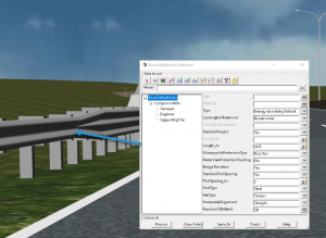
  • Creating trimeshes for pavements and roadside furniture
Introduction to 12d Model 14
Creating trimeshes from Tunnel Boring Machine (TBM) rings

12d Model 14 and Civil BIM

  • Large coordinates allowed – e.g. Eastings and Northings
  • Handles large and long horizontal projects
  • A Helix for arcs
  • Strings with and without diameters
  • Name/Code for strings – used in OZ and NZ since 80s
  • Null z values in strings
  • Drainage/Sewer pits and pipes
  • Tins for surfaces and trimeshes for 3D objects
  • Alignments
  • Linear referencing using Alignments
  • Transitions – spirals, cubic parabolas, NSW cubic parabola …
  • So yes, with 12d Model 14, BIM can be Civil!

12d View

  • 12d View is a FREE 12d Model project viewer.
  • 12d View can also read in data from a variety of sources
  • Just like 12d Model, 12d View has:
    • Plan, Section and Perspective views
    • Profiling on section views
    • Inquire options
    • Measure options.
  • 12d View can use:an existing 12d Model authorisationORan existing 12d View authorisationORrun unregistered

12d Synergy 3 and 12d Synergy 4

  • Latest versions support 12d Model 14.


All in all, a pretty action-packed introduction to 12d Model 14! Watch the video to see Lee’s full presentation!

New Webinar Series – Stormwater Drainage Design Fundamentals: Episode 1 – Project Preparation

Announcing…a new series of Training Webinars, to be run over the course of 2019, by Owen Thornton of 12d Queensland!

Owen has been writing software for 12d Solutions since 2003. He has a degree in Mechanical Engineering, a background in Computational Fluid Dynamics and 15 years professional experience in the civil and mining industries. He is the original author of the 12d Drainage Network Editor and the Drainage Analysis module, and a 12d specialist in drainage, utilities, plot parameter files, survey conformance, volumetrics, and system setup. Owen has recent consulting experience using  12d Model on a variety of large projects, to design: stormwater networks, industrial sites, landfills, dams, basins, channels, levees, access roads, rail sidings, car parks, building pads and retaining walls. These days, Owen also gives regular 12d training courses in drainage design and macro writing.

This new series of webinars – Stormwater Drainage Design Fundamentals – covers the basic and intermediate aspects of the Three Waters modules in 12d Model 14, with special emphasis on the design of stormwater drainage. It is presented as a condensed overview of the material normally covered in the first two days of the formal Three Waters training courses (W01 to W06) offered regularly by 12d Solutions. This material is assumed knowledge for many of the more advanced training courses available in the Three Waters suite.

A construction-ready drainage model – including catchments, pits, pipes, culverts, channels and flood extents – is created from scratch in 3D and designed for specified minor and major storm events using the Rational Method. Output plans, long-sections and calculation tables are also produced.

Episode 1 of the series – Project Preparation – was run on Wednesday 27th February 2019 – watch the video here. It details some of the preliminary steps required, before the drainage design can begin in earnest. Not all of these steps are mandatory, but they can certainly help to make the job easier.

Lot Pads (“Outside the Box”)

I caught up for a chat with Alisdair McCrudden of 12d Solutions WA, who first started using 12d Model – or, rather, 4d Model, as it was known then – in 1996! From 1997 he ran 12d Training courses through a reseller, and then in 1998 he commenced contracting directly to 12d, and has run our WA Support and Training ever since.

Alisdair shared some ways to think ‘outside the box’ with the Lot Pads options in 12d Model software. He informed me beforehand that whilst Peter Taynton has done some great videos (available on our 12d Model YouTube Channel) on these options…as is always the case with 12d Model, the tools can be used in ways other than they were originally intended!

In this great presentation, Alisdair takes us through some varying ideas to perhaps spur some thought on possible uses.

He examines the Lot Pads Create, The Lot Pads Edit, Dynamic Pad & Dynamic Pad/Pond options.

He also provided some ideas on:

  • Dynamically “floating” a Building Pad up & down to get a balance of earthworks quantities.
  • Grading a Parking Lot for drainage by selecting maximum & minimum grades to a gully via the “Level/Grade” option.
  • Creating a “plain” at a selected grade via the “Surface Grading” option.
  • Dynamically “float” a set of ponds + a surrounding edge platform, as 1 entity, up & down to get a balance of earthworks quantities.

Watch this great webinar video today!


–Lisa Stewart

Using a Drone

Surveyor of some 40 years and teacher at the Canberra Institute of Technology, Noel Burton of Detail Survey, addressed our 12d 2018 Technical Forum audience about using drones for surveying work.

Over his career, Noel said, he’s seen things progress from a non-technology type surveying right through to where we are at the moment, where he’s happily going out to use drones for most of his survey work.

The main focus of his talk was on using drones for those who don’t necessarily do so every day in the industry, to give a broad overview of what they can do.

What is a Drone?

A drone is currently known as a Remotely Piloted Aircraft (RPA).

Broadly speaking, there are two types of RPA – Fixed Wing and Multi Rotor. Fixed Wing RPAs fly like a plane whereas Multi Rotors will generally hover when you take your finger off the control.

Fixed Wings are the original RPAs used in surveying; they are traditionally launched from a catapult or manually propelled (thrown up in the air). These come with some issues, though – they require room to land, they’re quite expensive…and they’re apparently the favourite food of Wedge Tailed Eagles! Countless videos exist of these majestic birds taking exception to Fixed Wing RPAs, and while it’s quite funny to watch, it can also be a very expensive loss for anyone involved!

Multi Rotors, on the other hand, have been adopted more recently by surveyors, including Noel. Their popularity is down to a number of factors. They can take off and land vertically as well as hover, and they’re good not just for mapping but also for video and photo monitoring of structures such as power lines. They’re also quite inexpensive and easy to use, and their resolution and quality actually compare well even against some of the really expensive Fixed Wing RPAs. Oh, and as a sideline bonus, eagles, hawks and crows seem only amused by this strange ‘bird’ in their skies.

Rules for Using RPAs

The Civil Aviation Safety Authority (CASA) is the governing body for anything that flies in Australia. In the last couple of years, their rules have softened slightly. For instance, with Noel’s drone he can happily fly it and charge money for his services under their rules.

Their website lists the rules for flying RPAs – most are just common sense , but it’s important to know them anyway – Noel took us through some of the important ones. They cover things like only flying during the day, keeping the drone in your line of sight, not flying it above 120m, keeping it 30m away from other people, and never flying it near a bushfire zone. If a RPA is more than 100g in weight (which they pretty much all are), it needs to stay away from airports.

If you’re licenced as a drone pilot, you can apply to break some of the rules slightly. The corollary of this is that if you follow all the rules, you don’t need a licence according to CASA. However, Noel suggested talking to an insurance company as there could be liability issues if someone is injured by a drone, etc.

Planning Missions

Noel said that the first step to mission planning is to check whether you can fly a drone in your selected area – Google search ‘can I fly there?’ There are also phone apps available to assist with this. The result, either way, is that users can be notified of any restrictions in selected areas through use of an interactive map.

Noel’s next step is to get a surround. With a lot of the apps for flight planning, if you can create/receive a KML file of the extents of the proposed area for survey, you can use that as part of your flight planning. To get these, either use GoogleEarth yourself or get the file from the client.

After that, you can plan the locations for your Ground Control Points (GCPs) – i.e. the known points for being able to position the drone survey.

Some of the ‘fancier’ drones have accurate positioning in them so you don’t need GCPs, but with the more basic models, it is necessary to enter targets.

The spacing of the grid depends on how high you’re going to fly – if you’re going to fly high, you can have the lines further apart; if you’re flying lower to the ground, keep them closer together.

Once you’ve generated the KML file, we can bring it into an app that will run on the computer (or even an iPad). There are a few apps out there – Noel uses DroneDeploy. It does all the processing for you if you want to submit online; if you don’t want to do that it will design the flight plans for you and you can do the processing yourself (as Noel does – this method is free).

With this software, you can enter the height you want to fly, the forward and side overlap (sufficient overlap is necessary to create the 3D model), and the flight line directions.

Once you’ve generated the flight lines for the mission, you can calculate with the software how long the mission will take, the area you’ll cover, the number of photos, and the number of batteries you’ll use.

Noel showed footage of a mission that was completed using an iPad Mini and then simulated this mission live on screen for the audience, pointing out where the drone started taking the photos, and then what to do with those images/information.

Processing Data Gathered by RPAs

There are two main brands of processing software – Pix4D and Agisoft PhotoScan (now called Metashape). Noel uses Agisoft, which he says is fairly easy to use.

Agisoft – steps:

  • Adding photos
  • Deleting unwanted photos
  • Setting coordinate system
  • Aligning photos
  • Importing and referencing GCPs
  • Creating the point cloud
  • Filtering unwanted points
  • Creating mesh and imagery

Adding and filtering photos

The first step is to read in the photos taken by the drone and select the folder, then delete the ones you don’t want. You can then estimate the image quality – the program will go through to find the ones that aren’t high enough quality and get rid of those.

Aligning photos and referencing GCPs

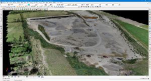
The photos are in latitude, longitude and height, and we convert them to MGA coordinates (the local coordinates). This is useful because when you survey the points they’ll use MGA and you need to be able to import them into the actual job to be able to manipulate the images. Also, there’s an option to align photos – the program will try to match pixels on the photos to build a model so you can read in your GCPs and identify them on the photos. It’s just a simple CSV file. Noel just uses regular black and white tiles for this – positions each on the ground as reference points for the photos. This gives you an idea of residuals to increase accuracy.

Creating and filtering the Point Cloud

When the initial point cloud is generated, it includes everything; running the Classify Points option allows you to filter out items such as trees, which are placed in different layers.

Creating mesh and imagery

We generate the mesh from the point cloud (just the ground layers). When we get the triangles, we can then use Decimate Mesh to filter out areas that are within a certain tolerance. From there it’s just a matter of getting out the rest of the processing. Each day, Noel gets things to a point where he can run this option overnight – batch process to build up texture, create imagery, export points (e.g. LAS), create a GeoTIFF file for accurate imagery, generate reports, etc.

Deliverables

Noel showed a KMZ file that came out of the job he was demonstrating, commenting that he finds using a drone for a job so much simpler and quicker than previous methods – he greatly appreciates this technology for saving footwork and increasing efficiency. The work has lots of applications. Noel concluded by stating that every Surveyor should have a drone on the back of the car – it is such an important tool these days.

12d Modellers on 12d Model

It’s always exciting to see the innovative projects that 12d Model is being used for. From the Parramatta Light Rail from to the West Gate Tunnel down in Victoria, seeing 12d Model in action is always illuminating for us as it is for other industry professionals.

One of the most useful things is finding out what features drafters and designers value best. Here’s a roundup of some of the feedback we got, from the people actually using our software…


Seb Woodland, GHD

I like the Computators and the way we can form parametric designs and really get a lot of design intent into the model, rather than just a 3D drafting type exercise.

Lane Irwin, 12d NZ

In 12d Model 14 for surveyors, definitely the plotting is going to make things a lot quicker and a lot easier. With the new 12d Field formats, just having a tree format will be absolutely fantastic, as well as more CAD options and things like that.

Carly Smith, Alexander Symonds

Personally, I love Visualisation. I used 12d Model a lot for a wind farm project, so we were able to plot out the turbines and then optimise the area and put in the roads, and it was great to fly through and see that all in visual.

Peter Murray, Brisbane City Council

I’ll go across all of the features, but the survey stuff is where I’m based. The new 12d Field is what I’m particularly interested in at the moment.

Dean Ostrofski, City of Gold Coast

Probably, the biggest benefit is the way 12d Model interfaces with a survey to design, then back to survey for construction set out, and now with the BIM capabilities, it’s fantastic. Visualisation has always been there, which is tremendous in being able to show our clients what we’re doing at an early concept stage before we go into the details.

Derek Roberts, Calibre

It’s probably starting to focus, the biggest one. There is probably the one point of truth. A lot more people are using it as a preferred software package, so it’s made it a lot easier to handle things and make changes and integrate with other software through common procedures.

Phil Weightman, Byrne Consultants

One of the features I particularly like is that everything keeps evolving within 12d. So that’s one of the great things, but I love how it’s starting to move into some of the object-oriented design space and how it’s keeping pace with the industry and also almost being on the leading edge of industry as well.


One thing we are certainly committed to at 12d is continually evolving and improving all of our software, to meet and exceed industry needs.

Going forward, we think the new user defined menus are going to be a game changer. There’ll be a nightmare for our support people because they won’t know what they’re going to be dealing with!  But I think a lot of users want to be able to customise 12d Model and chop it down for different applications.  We’ll still ship it with everything, but they can then define their own menus, top menu, side menu.

Ultimately, the future is shaped by our users coming and saying what they need that will make their life better. It might be some great big thing.  But it’s often the incremental changes that make the difference, such as cutting a task time from ten hours to one hour.