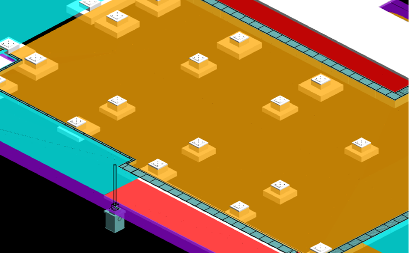
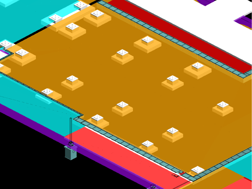
In a gas plant project, 12d Model was used to design civil engineering components for integration into PDMS (Plant Design Management System), supporting multidisciplinary design coordination.
However, PDMS did not natively support certain civil engineering elements, including road designs and TIN surfaces. Transferring civil design data required additional CAD preparation and manual editing, making updates time-consuming and increasing the potential for errors.
To address this, a custom macro was developed to automate the transfer of civil engineering elements from 12d Model to PDMS. Using configurable mapping files, the workflow could be adapted for different PDMS projects, reducing manual intervention and streamlining design updates.
The resulting workflow enabled more efficient transfer of civil design surfaces, allowing other disciplines to access updated information for design coordination and clash checking. It also preserved the flexibility of 12d Model for civil design modifications while reducing reliance on manual CAD editing.
This project demonstrates how 12d Model’s customisation and automation capabilities can improve data exchange and support multidisciplinary coordination in complex plant design environments.
Producing road and rail plans requires clear, well-organised annotation without compromising the visibility of other design information.
This video demonstrates the Super Alignment Style Output – Explode and Process Labels tool in 12d Model, which converts Super Alignment labels and symbols into individually named output models for more flexible plan presentation.
Key capabilities include:
Individual output models for each Super Alignment string.
Configurable label formatting, including trailing-zero trimming and start-of-alignment display options.
Flexible annotation placement to improve drawing clarity and minimise conflicts with other design elements.
Structured text and symbol naming to support downstream drafting and layer mapping in AutoCAD workflows.
For engineers and design teams preparing road and rail documentation, this provides greater control over annotation and the final presentation of design drawings.gineering
Calibre Rail, now part of WSP (https://www.wsp.com/en-au), played a key role in the Rowley Yard expansion for Fortescue Metals Group in Port Hedland, Western Australia, using 12d Model to tackle complex rail, earthworks and drainage challenges while supporting a cost-effective solution that saved more than AUD $2 million in capital costs.
Fortescue Metals Group (FMG) undertook a $US8.4bn expansion program to triple the size of its operations and take it to 155 million tonnes of iron ore per annum by mid 2013. FMG had a triplication of their rolling stock fleet. To meet the demand and the growth in associated maintenance procedures, an expansion of their existing facilities at Rowley Yard, Port Hedland was required.
FMG expansion plans ceased during the global financial crisis. As a result, the study and execution of their ambitious plans ground to a halt. Calibre Rail’s role as EPCM contractor was to take these preliminary studies and upgrade the mainline, which started in late 2010. With construction commencing on the other elements of the mainline (such as the triplication of the load-out loop, a new fuel facility and duplication of the mainline), there was little time to investigate the issues associated with Rowley Yard. A few of the issues faced include: – Earthworks modelling of both sub-grade and capping layer – Drainage issues and tying into the existing network – Service clashes – Development of a staged approach to the construction of the yard to minimise disruption.
20 options were investigated using the powerful ‘element method’ tools within 12d Model’s Super Alignment, with the turnout placement function providing a quick and effective method to arrange track layouts. Storm water drainage design was developed in 12d Model. Three options were investigated, limiting pipe sizes to 900, 1200 & 1500(mm). A cost/benefit analysis was completed that compared pit and pipe quantities and thrust boring sites. With the site 1600km away from the nearest pipe supplier, this decision was critical to logistics planning. “Using 12d to design this solution saved more than $AUD2million in capital costs for the project.” The storm water drainage design was independently verified. Diversion drains were mapped in 12d Model using the HEC RAS writer. Importing the water surfaces from HEC RAS to 12d Model was used to then calculate tail water conditions.
“12d modelling isn’t just a click of a button. It often takes many attempts to find a solution to a problem. In a brown field environment, where little planning had been done in the past…issues were constantly faced. “It seemed that everything we touched was broken and every solution we tried to implement failed. This led to blowouts in the delivery, but we are very happy with the result thanks to 12d Model and its vast array of tools.” —Chris Compton, Fortescue Metals Group
For new 12d Model users, the software can initially feel overwhelming. With its many tools, menus, buttons and layers of information, getting started can seem like a steep learning curve. For civil engineer Rule Falkstrom, who has more than five years of experience designing and supervising civil infrastructure projects across Queensland and New South Wales, learning 12d Model was largely a self-taught journey. His approach was simple: use every project as an opportunity to learn. Working across stormwater, pavements, driveways, car parks, sewer and water design allowed him to gradually build his knowledge while gaining practical experience. He also found that seeking advice from colleagues and other experienced users, even those who did not use 12d Model, helped him approach problems from different perspectives.
One of the most valuable resources in his learning journey was 12d Model’s range of free learning resources. Webinars and videos provided answers to most of his questions, covering topics such as earthworks, road design, stormwater, IFD data, super alignments and geometry. When a more specific question came up, the 12d Model online forum provided another valuable source of information, often revealing that someone else had already encountered and solved the same problem. For questions that could not be answered through these resources, contacting 12d Model support directly provided another avenue for assistance. The 12d Model manual was also useful for discovering small features and shortcuts that could significantly improve efficiency, such as using the middle mouse button for selection and learning more about snapping and drafting tools.
These techniques became particularly valuable on a recent detailed design project for a constrained service station site. The project involved stormwater and OSD design, pavement and earthworks, frontage works, and multiple stakeholders with different requirements. The site also had challenging level and gradient constraints involving the OSD outlet, fuel station bund, vehicle access, car parking, pedestrian paths and a future development stage. With so many interconnected elements, changing one level could affect multiple parts of the design. Pad grading tools proved especially useful because they made levels and grades easier to visualise and allowed different areas of the site to be adjusted efficiently. Contours, arrows and 3D views also provided useful visual cues, helping identify drainage paths, grade changes and potential issues that might not be immediately obvious in plan view.
The experience highlights an important lesson for both new and experienced 12d Model users: the software does not have to be mastered all at once. Understanding the tools available, learning 12d Model’s terminology, and using features such as pad grading, replication, snippets and templates can reduce repetitive work and make complex designs easier to manage. By combining practical project experience with webinars, videos, the online forum, the manual and support resources, users can gradually build confidence and allow the software to do more of the work for them. For self-taught users especially, consistent practice and making full use of available resources can turn an initially complex interface into a powerful part of the civil design workflow.
When the deadline is the Olympic Games, there is little room for redesign, delay or coordination issues.
When London was selected to host the 2012 Olympic Games, the city had to deliver large-scale venues and infrastructure capable of supporting approximately 24,000 athletes. The Olympic Village site presented an additional challenge: it was located within an already developed urban environment, constrained by surrounding infrastructure including a high-speed rail link, while also requiring new roads, earthworks and utilities to support the Games.
For Arup, the scale and complexity of the project called for a different approach to civil design. Stakeholder feedback meant that design options would continue to evolve, while contractors were already working to demanding construction programmes. Changes therefore needed to be assessed quickly and translated into construction documentation without disrupting the wider design.
Arup implemented 12d Model to bring the civil design together in a single, connected model. Earthworks, roads and utilities were modelled within 12d Model, allowing designers working on different elements to reference shared design information and coordinate their work.
This was particularly valuable for the site’s extensive subsurface utilities. By modelling the utilities alongside the other civil elements, the team could identify potential clashes during design rather than discovering them during construction. As the design developed, 12d Model’s automated recalculation capabilities also allowed options and changes to be tested quickly, making it easier to assess their impact across the wider site.
The complete 3D model provided another important advantage. Arup and the client could review the civil design from all angles before documentation and construction, helping them assess how roads, earthworks and underground services would work together within the constrained site.
Once the design was confirmed, the model could be used to produce the documentation required by construction contractors. Automated processes and reusable standard components helped reduce manual work and accelerate the design cycle, supporting the project’s demanding programme.
The result was a more connected design process that allowed Arup to develop, coordinate, review and document the civil works within a single model, helping keep pace with one of the world’s most time-critical infrastructure projects.
As the project team noted:
“The modelling of all subsurface utilities in 12d Model was the ultimate design solution to prevent problems during the construction phase.”
The London 2012 Olympic Village is a strong example of how integrated civil modelling can help engineering teams manage complex sites, respond to changing requirements and make critical design decisions before they reach construction.
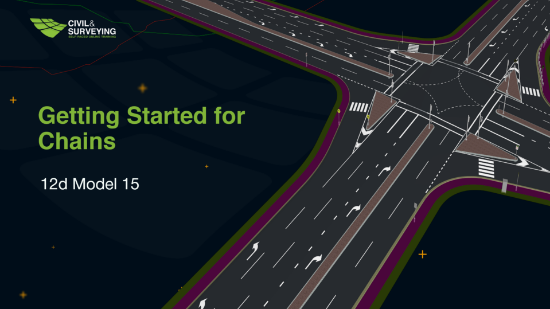
As 12d Model projects become more complex, repeating the same sequence of tasks can become time-consuming and difficult to manage consistently. Chains provide a powerful way to turn these sequences into repeatable workflows that can be run when and where they are needed.
The Getting Started with Chains – 12d Model 15 course introduces the principles behind creating these automated workflows and demonstrates how they can be adapted to different project requirements.
Participants will learn how to capture existing 12d Model panels and combine them into workflows, introduce parameters and user prompts, and use conditional logic to control how a Chain responds to different inputs. The course also explores practical applications such as controlling model visibility through view favourites, using parameters to generate multiple road plots from a single PPF, and configuring Grid parameters.
As workflows become more refined, Chains can also be connected to custom menus and toolbars or configured to run automatically when a project starts. The course also introduces compiling Chains as a way of protecting the intellectual property contained within customised workflows.
With 2 hours and 21 minutes of on-demand training across 10 lessons, the course provides a practical introduction to one of 12d Model’s key workflow automation tools. Participants can work through the material at their own pace and test their understanding through practical quizzes.
The course is free to enrol and includes a 3-month 12d Model v15 training licence, Certificate of Completion upon meeting the requirements, and unlimited access to SPOT video lessons.
Super alignments are a powerful string type in 12d Model that allows horizontal and vertical geometry to be managed independently within a single string. Unlike a standard super string, a super alignment can contain its own horizontal geometry—such as straights, curves and transitions—and vertical geometry, including grades and vertical curves. This makes super alignments particularly useful for design applications where both the plan and profile need to be controlled independently while remaining linked through chainage. In 12d Model, super alignments are commonly used for road and rail design, airport runways and taxiways, drainage channels, and other civil infrastructure projects.
One method for creating a super alignment is the IP (Intersection Point) method, which builds the horizontal alignment by establishing horizontal intersection points (IPs). The initial straights are defined through the IPs, after which curve radii and, where required, transitions or spirals can be added. The vertical component can then be developed separately using vertical intersection points (VIPs), grades and vertical curves. This approach gives designers greater flexibility when refining an alignment, including the ability to insert specific grades over a set distance, change existing grades, add vertical curves, or position IPs precisely using coordinates and CAD snaps.
Creating a super alignment in 12d Model starts from Strings > Super Alignment > Create a Super Alignment, where users can define properties such as the string name, model, colour, starting chainage, labelling style and whether the alignment should be closed. Advanced settings also allow a super alignment to be configured as a pipe or culvert, with options for its justification and size. During editing, dedicated super alignment tools can be used to add or move IPs, insert curves, extend geometry, adjust grades and refine the horizontal and vertical design. These specialised tools are important because super alignments are a unique string type and have their own editing functions.
Existing strings can also be converted into super alignments, making the workflow useful when working with survey or CAD data. Individual strings can be converted through Strings > Convert > Super Alignment, while multiple strings can be processed through Utilities > A to G > Convert > Super Alignments. When bringing CAD geometry into 12d Model, separate lines and arcs can first be joined into a single string using the Head to Tail utility before conversion. The conversion can then be performed using either the IP or Element method. Once converted, the dedicated super alignment tools can be used to apply labelling styles and further edit the alignment, providing a practical workflow for turning existing design geometry into a fully editable horizontal and vertical alignment in 12d Model.
Super Alignment Computators and Components in 12d Model provide a flexible way to create more efficient and responsive civil engineering designs.
In this training session, 12d Model trainer and technical support specialist Rod Burns demonstrates how Computators can be used to connect road alignments and maintain relationships between different elements as a design changes.
Smarter Alignment Design with Computators
Super Alignment Computators are calculated geometric elements that can reference other parts of a design. Rather than relying solely on fixed coordinates, they can recalculate their position when referenced geometry is moved or updated.
This is particularly useful when connecting road alignments. As demonstrated in the video, a referenced line can be used to calculate the intersection between two roads. When one alignment changes, the connected geometry can be recalculated to reflect the new position.
Computators can also be used with horizontal and vertical geometry, providing greater flexibility when developing road designs.
Using Components in 12d Model
The session also introduces Components, which can be used to create and manipulate reusable design geometry. These can be especially useful when adapting designs to different project conditions, including moving from Greenfield to Brownfield environments.
Together, Super Alignment Computators and Components can help reduce manual editing, improve design consistency and make design changes more efficient.
Watch the Full Video
Want to see these workflows in action?
Watch Rod Burns’ full session on Super Alignment Computators and Components for practical examples of how these tools can be used to create smarter and more responsive designs in 12d Model.
Explore more 12d Model training and resources to build your civil design skills and improve your workflow.
Aurecon Jacobs JV played a key role in the West Gate Tunnel Project ( in Victoria, working alongside CPB and John Holland to tackle the complexities of one of Melbourne’s major infrastructure projects, with 12d Model supporting accurate, coordinated civil design and project delivery.
The West Gate Tunnel Project is broken up into 3 sections – the West Gate Freeway (out west), the Tunnels (in the middle), and the Port to City (in the east).
The Freeway section involves upgrading from eight lanes to twelve, including an express lane between the M80 Ring Road and the West Gate, and 4 interchange upgrades.
The summary on the West Gate Tunnel website lists:
Extra lanes on the freeway between the M80 Ring Road and Williamstown Road
Entry and exit portals where the tunnels connect with the West Gate Freeway
Ventilation structure at the tunnel exit to remove air from inside the outbound tunnel
Interchange upgrades at the M80 Ring Road, Millers Road, Grieve Parade and Williamstown Road
Ramps to Hyde Street to connect trucks directly with local industry
Noise walls to reduce traffic noise for residents and open spaces
Walking and cycling paths to complete missing links in the Federation and Kororoit Creek trails and better connect communities, including new overpasses over Williamstown Road and Stony Creek
Pedestrian bridges replacing the existing overpasses
Freeway Management System to support good traffic flow and safety
New open spaces and planting thousands of trees and other plants in the freeway area.
The Tunnels component includes two three-lane tunnels, one inbound tunnel of 2.5km and one outbound tunnel of 3km – all to take motorists and trucks off residential streets.
The website also lists:
Twin tunnels under Yarraville between the West Gate Freeway and the Maribyrnong River
Entry and exit portals where the tunnels connect with surface roads
Ventilation structures at each tunnel exit to remove air from inside the tunnels
Walking and cycling paths on Hyde Street, Harris Street, Maribyrnong Street and a bridge over Whitehall Street
New landscaped open space in Altona North and Footscray
Freeway Management System to support good traffic flow and safety
Tunnel safety features for smooth operation of the tunnel, including automatic detection for over-height trucks, fire systems and emergency access and exits.
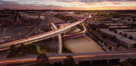
The Port to City section involves a new bridge over the Maribyrnong River River to connect the tunnels, with an elevated roadway along Footscray Road connecting to CityLink, Dynon Road and Footscray Road, running above the centre of Footscray Road, as well as direct links to Port of Melbourne, CityLink and an extension and widening of Wurundjeri Way.
The website also lists:
Ramps to the port at MacKenzie Road and Appleton Dock Road for direct freeway acces
Walking and cycling paths for quicker and safer cycling to the city with a new veloway and bridges over Footscray Road and Moonee Ponds Creek
Extending Wurundjeri Way north to Dynon Road to create a city bypass
Freeway Management System to improve traffic flow and safety
New open spaces and planting thousands of trees and other plants in the freeway area.
Design Production – Workflows
12d Model and 12d Synergy are both in use on this project, along with various other packages.
12d Model was selected to do the long sections and cross sections across the entire job, as well as the modelling of the tunnel components and the bridges over the Maribyrnong River.
The team needed to develop efficient processes for bringing in data from other packages. They worked out the best workflows for them, with particular attention to consistency across the entire project.
With their incoming 2D CAD and 3D Models, the main advantage of 12d Model was that they could copy sections of the bridge and tunnel modules and make sure everything was aligned. The process they came up with was running a Chain for each 2D Drawing and each 3D Model that would create a project for each DWG, and then in that Chain they’d also create a date stamp model and use a 12d Synergy search to look for that date stamp model (and compare against a search in another package). From there, they’d work out what was out-of-date and re-run just that Chain.
The team copied DWG files to the 12d Synergy Server and gave them their own Chain, Project, and Mastershare labels – applying a naming convention. Dummy models were created at chain runtime (date analysis). Ongoing date modification analysis was performed using Excel Queries. 12d Synergy was their single source of truth.
Custom Reporting
The team needed a lot of custom reporting due to other software packages being used, with different types of reporting requirements. They learnt to be prepared on the BIM journey for ‘curly’ output requirements, and to ‘make friends with’ Excel and VBA.
They experimented with XSLT Files (12d Report Definition Files), and adapted to Legacy Workflows developed on previous jobs for MX (the hand they were dealt).
The next challenge was how to get data out of 12d Model so it could go into Dynamo and Revit to produce the tunnel rings – for this they enlisted Matt Monk to create a macro to report the perpendicular points between the centre of the tunnel and report it back to the control road which is not in the centre of the tunnel.
Chain Usage
Users were upskilled on how to use parameters in their chains – this happened on the job, with great success.
Custom Widgets were created, with Prompt Result Inputs – (yes, no, cancel). The ‘cancel’ widget was particularly useful in case something fell over halfway through running of the Chain.
Two of their favourite uses were:
Prompt Result Values > PVFs for filename concatenation
Using Widget button to pick result and GoTos they could loop within chains (also very nifty) – naming something differently each time it was used on any number of strings
They employed one Road Design Output PPF per Zone with multiple PVFs, leading to a huge process improvement to the speed of their output, which was noticed by users.
Snippet Usage
Road Barriers – used extensively – need penetration details on stormwater pits; option to change height of first string/extend barrier
Kerbs
Vehicle Clearance and Roll Allowance (AGRD and RTA values) – vehicle clearance was a parameter set by the project (going under bridges etc.) but the sway envelope allowed gathering of AustRoads figures – design speed, left and right crossfall, etc.
L-Shaped Retaining Walls – ability to insert after a string, etc. Means you can set wall thickness, vertical offset to top string, footing RL, footing thickness, leg length forward/back – quite dynamic and went together pretty well
Road Deck Slabs/multi-floor tunnel portals for space proofing – took existing 12d 2-point slab snippet and added ability to put crossfall, RL, etc. Insert a string higher up in MTF and be able to trace it. Pavement Wearing Course (for XSs)
Sign Legibility (Guide to Traffic Management: Traffic Control Devices) and Sight Line – input speed, sign dimensions, offset to control line, how many words on sign, type of vehicle, number of lanes, etc. -> draws a mesh with sign in distance and ability to profile string
ITS Trenches by Trench Type/make your own (experimental at this stage)
Also experimented with Sub-Soil Drains (how to attach to a pavement layer and such) and Trench
Structure items modelled in 12d Model as space proofing prior to modelling
Tunnel Mesh
Tunnel Portals
Basic Bridge Crossings
2D Road Design Exports
PVFs within Chains used extensively for exporting hundreds of DWGs
Naming Convention Control
Consistency
Repeatability
Quickly expandable
Temporary Entity duplication > String Info Change
Long section/cross section MESH colour control
Label style manipulation
Not good for point count with MESHES
3D Road Design Exports
General
Road TRIA, MESH and STRS > DWG and IFC > Navisworks
Road TRIA, MESH and STRS > SML > Contractor Setout
The Department of Transport and Main Roads, Queensland, undertook the preliminary design for approximately 12 kilometres of the Kennedy Highway in Queensland, Australia. The highway travels west from Cairns through Kuranda and on to Mareeba, connecting the coast with the tablelands. The project crosses the Macalister Range and passes through the Wet Tropics World Heritage Area, creating a challenging environment in which to develop and communicate the proposed upgrade.
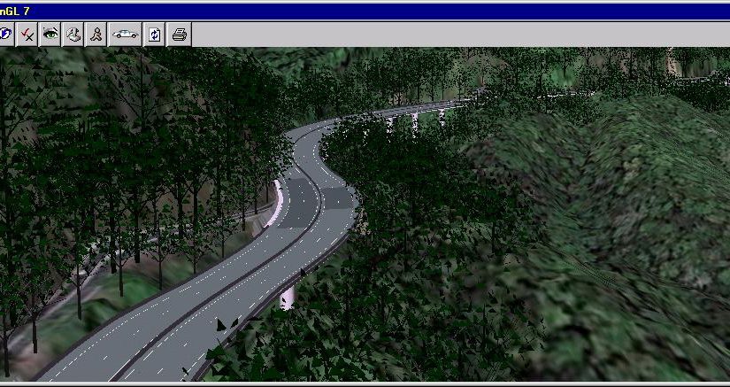
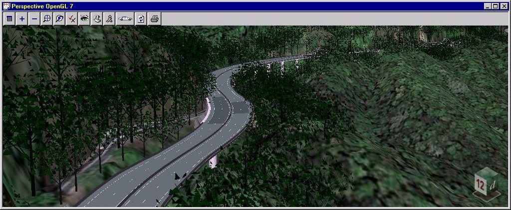
A key part of the project was developing a realistic representation of both the existing environment and the proposed highway, allowing the design team to visualise the project before construction.
Building the Existing Environment
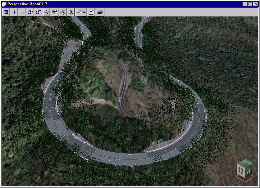
The existing terrain was constructed from airborne LiDAR data collected by helicopter, providing the foundation for modelling the project area. Aerial photography was then draped over the resulting triangulation to create a realistic representation of the existing landscape.
This provided a detailed terrain and visual context in which the proposed highway could be developed and assessed.
Developing the Highway Design in 12d Model
The concept design for the new highway was developed using 12d Model, incorporating not only the road design but also key infrastructure and environmental features.
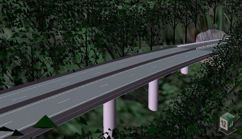
The first half of the project included 28 of the 34 bridges, which were modelled using super strings. Roadside barriers and vegetation were also modelled in 12d Model, creating a more complete representation of the proposed highway and its surroundings.
By bringing these elements together with the existing terrain and aerial imagery, the team could assess the proposed infrastructure within its wider landscape context.
Creating a Virtual Fly-Through
The project team used the 12d Model environment to create virtual fly-overs, drive-throughs and selected views of the proposed highway.
These visualisations provided an opportunity to view the proposed route from different perspectives and understand how the highway, bridges and other infrastructure would appear within the surrounding terrain. The drive-through for the final section of the highway was also subsequently completed with the aid of 12d Model.
Visualising the Project Before Construction
The completed model provided a realistic representation of how the upgraded highway and surrounding area could look following construction and regrowth.
Being able to virtually drive along and fly over the proposed highway before it was built gave the project team a practical way to communicate and review the preliminary design. It also helped provide a clearer understanding of how the proposed road and structures would integrate with the existing landscape.
The Kennedy Highway project demonstrates how 12d Model can combine survey data, terrain modelling, civil design and 3D visualisation to provide a more complete understanding of a proposed infrastructure project before construction begins.