
History Files: Engineering the Auxiliary Spillway at Warragamba – SMEC

In collaboration with the Sydney Catchment Authority, SMEC harnessed the capabilities of 4D Model (now 12d Model) to design and deliver key components of the Warragamba Dam Auxiliary Spillway project, enhancing design accuracy, visualisation, and earthworks management for a major infrastructure upgrade.

The major source of Sydney’s water supply is Warragamba Dam. Australia’s fourth largest dam, its primary function is to provide a water supply for the Sydney Metropolitan area. When adequate quantities of water are stored to meet these needs, electricity is generated and fed into the NSW grid by the hydro-electric power station located at the base of the dam.

Warragamba Dam is in the High Incremental Flood Hazard category and to prevent overtopping of the dam in extreme flood events, an auxiliary spillway is being constructed adjacent to the dam to divert floodwaters in excess of the capacity of the existing spillway.

The auxiliary spillway is a major civil engineering project due for completion in mid-2001. The works are being undertaken on a design and construct basis for the Sydney Catchment Authority (previously known as the Sydney Water Corporation) to improve the safety of the dam. In December 1998, the contract for the design and engineering of the spillway was awarded to SMEC, the Snowy Mountains Engineering Corporation.

The project involves major excavation – some 1.8 million cubic metres of sandstone and overburden is being removed and transported to a spoil emplacement – and the concrete lining of the auxiliary chute spillway which will be approximately 650 metres long and drop 50 metres before discharging to the river.

Five fuse plugs – embankments that are designed to wash away when overtopped – are being built at the upstream end of the spillway chute to prevent the auxiliary spillway from operating in flood flows smaller than about a one in 750 chance of occurrence in any year.

Generally, the floor and wall of the spillway chute are in the form of a reinforced concrete lining against the excavated rock surface, however, one section of the spillway over an existing creek line will be constructed on compacted fill with cantilever walls on either sides. A bridge across the spillway, and a new road, are designed to provide access to the crest of the dam, the Valve House and the hydro-electric power station at the base of the dam.

Following concept design carried out by the Department of Public Works and Services, SMEC is responsible for the development of the detailed design – from concept to production of construction drawings. A vital component in SMEC’s engineering design work is 4D Model (later renamed 12d Model) software. Design draftsman on the project, Michael Kurtz, says it contains all the options necessary to produce a digital terrain model (DTM), including fast triangulation, contouring and sectioning routines, and to calculate spill volumes for accurate placement and subsequent costing of the work carried out.

Warragamba Project Manager, John Gray, said 4D Model software was primarily used for design and modelling of the auxiliary spillway and associated access structures such as roads and the bridge approach, along with calculation of spill volumes.

“Using 4D allows us to continually modify designs,” Michael said, “and, most importantly, to do it quickly. 4D allowed us to complete re-designed versions very fast for presentation to the client and to show the designs interactively in plan and sectional views. We also had to continually modify the design to fit the spoil emplacement within specified confines nominated by the client. The spoil would not fit into the area initially defined and required many modifications of the design.

“The perspectives we can provide using 4D are an easy way to convey a design to people who find engineering plans and contours difficult to interpret,” Michael said. SMEC uses the 4D alignment module to construct strings consisting of horizontal and vertical geometry. These horizontal and vertical components are created and edited interactively using the IP method on plan and section views.

SMEC is also using the 4D Drainage Module in the Warragamba project. This module supports the display of drainage networks typically required for development projects and new land subdivisions. An added bonus SMEC encountered using 4D was the ease with which the model output could be checked at any stage of the design process.

Following development of a design component, a copy of the model was produced for checking and further development by design engineer, Tim Loffler. Tim, who had no previous training in the software, said he found it “a most intuitive package” and that he could view and interrogate the model after getting a feel for the way in which the program operates.

“The program is very robust and will faithfully do what you ask it to do,” he said.

Download this Case Study as a PDF HERE.

12d Tech Forum 2026 – Gala Dinner Sponsor (Stantec)

At the 12d Tech Forum 2026, most of our delegates will attend the Gala Dinner and enjoy award-winning food in BCEC’s beautiful Plaza Ballroom. 

We’d like to take this opportunity to thank our Gala Dinner Sponsor, Stantec, for their generous contribution towards what will surely be an incredible night. 

Stantec is a global leader in sustainable engineering, architecture, and environmental consulting, and are long-term 12d users. 

Register for the 2026 12d Tech Forum: www.12dtechforum.com 

More about Stantec: www.stantec.com 

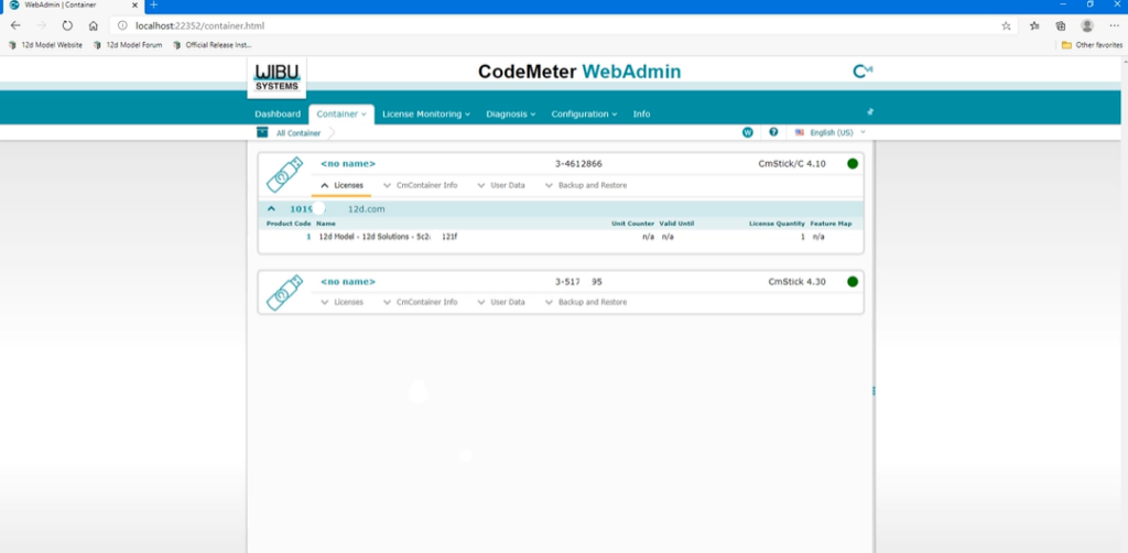
The Tipster: CodeMeter WebAdmin

If your organisation uses a network CodeMeter dongle, proper server configuration is essential to ensure all 12d Model users can access their licences.

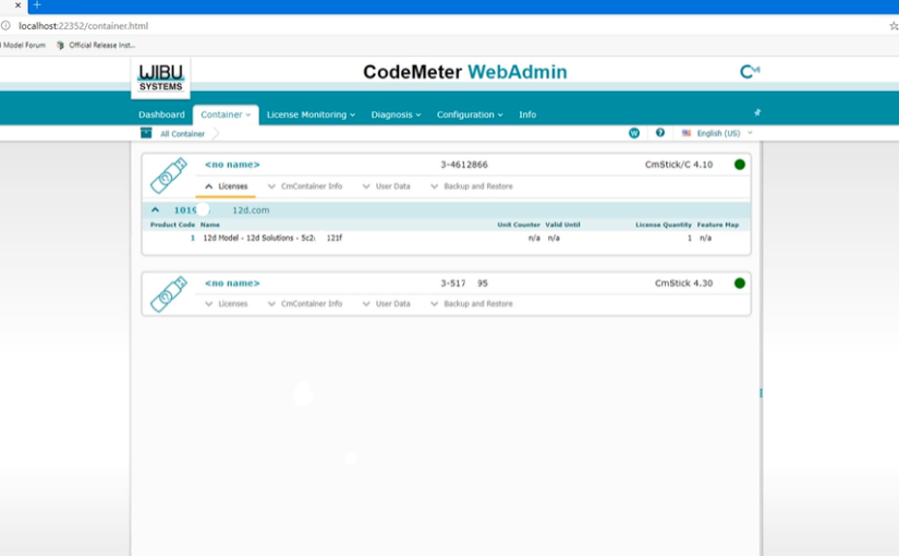
In this tutorial, we introduce CodeMeter WebAdmin, the management interface used to configure and monitor network licensing. You’ll learn how the CodeMeter server and client setup works, where to find your dongle’s unique CodeMeter number, and how to enable network server access so licences can be shared across your organisation.

Whether you’re setting up a new server or troubleshooting an existing one, this video provides a practical introduction to one of the key components of 12d Model network licensing.

Watch the full tutorial to learn how to configure CodeMeter WebAdmin and get your network licensing environment running smoothly.

History Files: 12d Model helps to build Queensland’s Smart Road – John Holland Construction/Barclay Mowlem Pty Ltd

Queensland Department of Transport and Main Roads’ Pacific Highway Upgrade (Logan to Stapylton section), delivered by John Holland/Barclay Mowlem JV and supported by Robert Smith’s implementation of 4D Model software, demonstrated how advanced digital modelling streamlined the construction, volume calculations, and survey management of Queensland’s largest road infrastructure project.

One of the most heavily trafficked routes in Australia is the Pacific Highway between Brisbane and the Gold Coast. Traffic using that section of the Pacific Highway has increased more rapidly than on any other highway in Australia, quadrupling since the road was built in the 1960s.

To address the problem of the increasing strain of south-east Queensland’s transport infrastructure, the Queensland State Government has developed an Integrated Regional Transport Plan for the region.

Part of this plan is to upgrade the Pacific Highway to an eight and six-lane Motorway between Logan, just south of Brisbane, and Nerang, on Queensland’s Gold Coast. A Queensland Department of Main Roads project, it is the largest road project ever undertaken in Queensland and is to be completed by September 2000.

For construction purposes, the 43km Motorway project has been divided into six sections with contracts awarded to a variety of engineering firms. The highest value contract – $120 million – was awarded as a joint venture to John Holland Construction/Barclay Mowlem Pty Ltd for eight lanes for the section Logan to Stapylton, a distance of 7.4km, due for completion in March 2000.

Integral to construction of this section of the Motorway, is the use by the John Holland/Barclay Mowlem Surveying Department of 4D Model (later renamed 12d Model) software.

Robert Smith, the surveyor primarily responsible for running the computing operations of the joint venture’s Surveying Department, has developed an application based on 4D Model which, he explained, “allows me to manipulate the huge amounts of data involved to create the individual layers which make up the road and extract various quantities out of it”.

His application involves taking the initial output, received as design files and natural surface files, from Queensland Main Roads and, using 4D, to convert this data into what he describes as “useful 4D data sets”. Robert then creates cross sections on various alignments and applies 4D Model’s boxing or template functions to create various layers which are then triangulated.

The volumes of various materials used in the different layers which comprise construction of a road – from the embankment layer through the various layers of gravel on top of that, to the paving and bitumen components – are then calculated in order to determine the quantity for payment purposes on completion of the work.

The design files are also used concurrently with traditional plans to aid the construction process. Macros are used to create files for “TP SETOUT” software, run by the field surveyors in their HP 200 palm top computers.

From data in the natural surface file and survey data collected by site surveyors, further ‘layers’, such as existing ground, existing underground services, are created in data sets to aid the construction process. This means potential clashes between the profiled string and services, such as telephone lines, electricity cables, gas lines and drainage and water pipes, are easy to detect. In a further step, an existing ground model is triangulated for future volume calculations.

Triangulation has options to calculate surface area, depth contours (isopachs) and the intersection of triangulations, and options for slope, aspect and viewshed analysis. Colour coding can be used for the slope and aspect analyses.

The advantage of using 4D Model, Robert says, is that in the manipulation of all the data the ‘layering’ steps entail, “4D lets us run unlimited data sets and points and it’s very fast at running volumes”.

He says 4D Model’s boxing, template and volume computations have “made the job a lot easier and faster, and its interactive capabilities provide immediate feedback at every stage. It is also easy to use,” he added.

Download this Case Study as a PDF HERE.
12d Tech Forum 2026 – Coffee Cart Sponsor (C.R. Kennedy) 

When you’re at the 12d Tech Forum 2026, enjoying a cup of delicious barista-made coffee from Brisbane-based coffee cart geniuses Gathering Events, we hope you’ll take a moment to be thankful for our Coffee Cart Sponsor, C.R. Kennedy! 

C.R. Kennedy provides a complete range of construction solutions for each phase of the construction lifecycle, helping boost productivity at every stage. Their construction solutions increase efficiency and allow projects to be completed on time, on budget and to the highest specifications. 

Register for the 2026 12d Tech Forum:  www.12dtechforum.com

More about C.R. Kennedy:  https://www.crkennedy.com.au/

The Tipster: Setting Up Dongles.4d File

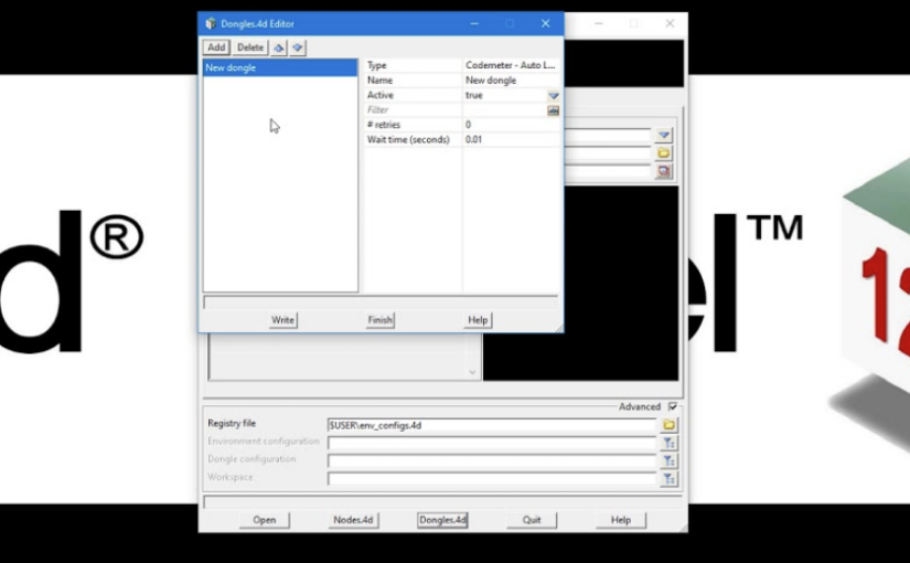
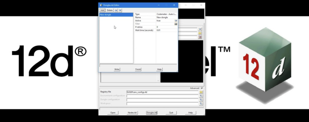
In this short but important tutorial, we explain how 12d Model accesses licenses using CodeMeter dongles and how a simple configuration file can help the software locate a valid license.

Whether you’re using a standalone dongle connected directly to your workstation or a network dongle shared across multiple users, understanding how 12d Model searches for licenses can help prevent setup issues and save troubleshooting time.

You’ll also learn about the dongles.4D file, which controls where 12d Model looks for a license and in what order. While standalone users typically won’t need to modify this file, it plays an important role in networked environments.

Watch the full video for a clear walkthrough of dongle-based licensing and learn how to ensure your 12d Model installation is configured correctly from the start.

History Files: North Kiama Bypass – Roads and Maritime Services NSW

For the North Kiama Bypass project in New South Wales, Australia, RMS NSW, with Project Design Supervisor John Burns, utilised 4D Model to rapidly develop an award-winning interactive presentation that supported planning approvals, enabled real-time design evaluation, and showcased the power of digital modelling in complex transport infrastructure projects.

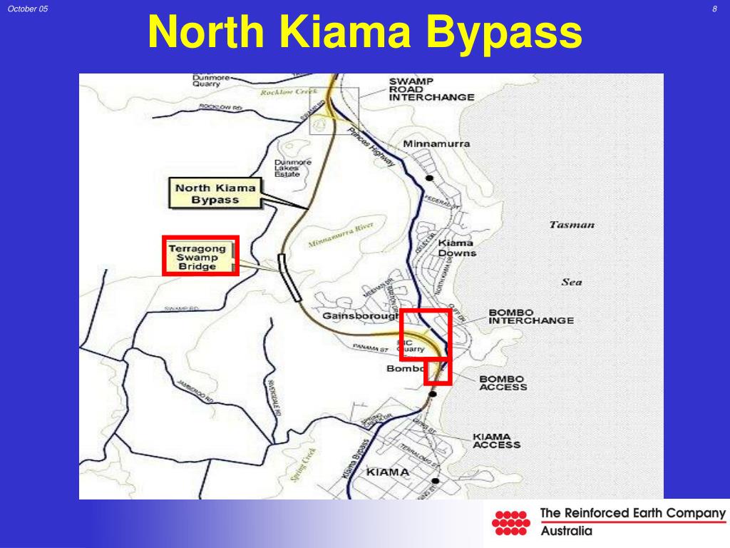
A presentation on the proposed North Kiama bypass, developed by the RTA (Roads and Traffic Authority) Wollongong’s Technology Branch using 4D Model civil and surveying software, has won an RTA Technology Merit Award for outstanding achievement. The presentation, using a laptop computer and overhead screen, was produced for the Commission of Inquiry into the bypass and according to John Burns, Project Design Supervisor, RTA Wollongong, it was received extremely well by all present.

“And what was even more pleasing was that the whole presentation was developed in under four weeks to meet a very tight deadline,” said Mr Burns.The North Kiama bypass project had been going on for around 10 years, due largely to the fact that it impacted on an environmentally-sensitive wetlands area. The local council had refused to approve the project, so it had to be put in front of a public hearing, or Commission of Inquiry, in order to gain State Government approval. The RTA received notification that the Commission of Inquiry would take place in six weeks time.

“We had to decide in a hurry how we would prepare our presentation,” said Mr Burns. “We had to come up with something which could be done quickly but which would be accurate and also be ’live’ so that we could answer ’what-if’ questions on the spot.

“We were long-term users of Moss for road design work,” he said. “It’s a good design tool but not one which you can use for quick and accurate concept work, which was what was needed as we had to present the Commission with options for the bypass route.”We had seen 4D Model previously, so knew it was exactly what we needed to do such a job in a hurry. To make sure it could be done, we asked Lee Gregory from 4D Solutions to come down and carry out an on-site demonstration of the capabilities of 4D Model.

“We then produced a quick business plan submission and obtained approval to purchase the software. It was installed quickly but by now we only had four weeks left to go until the Commission of Inquiry. We knew that, with such an extremely tight time-frame, we would not have time to train-up on 4D Model ourselves, but we had a competent operator elsewhere in the RTA in the form of Ray Tester from our Wagga Wagga office, who was a very experienced 4D Model user. Ray was seconded, on a part-time basis, to help us out, and things got underway,” said Mr Burns.

The initial steps for the RTA were to obtain digitised contour maps of the area, plus cadastral information and aerial photographs to locate and define vegetation limits and sensitive wetland areas. This information was used to start building up layers using Microstation to create the base model. This base model was then put into 4D Model and detailed concepts, interchange layouts, earthworks, boundary details and options were established.

“We wanted to be prepared from the first day of the Commission to be able to answer any design questions and present alternatives for the Commissioner, the members of public and the RTA personnel present, in a quick, accurate format,” said Mr Burns. “With 4D Model we were able to do this very quickly and present the updated information on screen.

“Everyone was very impressed with the speed and quality of the presentation,” he said. “4D Model also allowed us to do a walk- and drive-through video presentation, which helped clarify everyone’s perceptions of what the bypass would look like and, we believe, helped with the final decision. Ray Tester’s skills in the use of 4D were crucial in the design and presentation of this project. He obviously did a great job, as not only was the reception at the Commission excellent, but we subsequently received the RTA Merit Award.

“We are, of course, still using 4D, and we now have two licences servicing 15 workstations,” said Mr Burns. “I can’t praise 4D enough and their product support is also great.

“We used to produce our initial concepts by hand from contour plans then go into Moss,” he said. “This was satisfactory for simple jobs but created problems with complex projects. Now we start with 4D Model and produce the horizontal and vertical geometry, earthworks and cross-sections then go into Moss for the final design, and we obtain a much better result. We are currently investigating the purchase of software which will enable us to scan ortho/topo maps, build up a 3D model from this and then use 4D to produce an electronic, instead of a hand-produced, concept,” he said. “Then we’ll see an even bigger improvement”

Download this Case Study as a PDF HERE.
The 12d Tech Forum is Turning 21! 

Way back in 2005, when we first began hosting the 12d Tech Forum (which was then called the 12d User Conference), we had no idea the event would have such success and longevity. 

In 2005, we were thrilled to have the support of 291 12d Modellers joining us in Brisbane at the Convention and Exhibition Centre (BCEC) we’ve come to think of as a second home. Back then, the Centre itself was much smaller, too! 

Flash forward to 2024 and we were not only in a bigger section of BCEC – the Boulevard Level, which we’ve used for our events since 2012 – but we’d sold it out completely! Over 630 delegates moved around those hallowed halls over the three days of that event, and we could not have been happier. 

And now, as we prepare for our 2026 event, we’re so excited to be moving into an even bigger space – upstairs on the Plaza Level…and to be celebrating the 21st birthday of our event! 

We’d love to see you there to celebrate the 12d Tech Forum ‘coming of age’ – register through 12dtechforum.com today! 

Image credit: EsterFoster

The Tipster: Installing Dongle Drivers 

Before installing 12d Model, it’s helpful to understand how its licensing system works. This video gives you a clear and simple explanation of the different dongle types you may receive after purchasing your license.

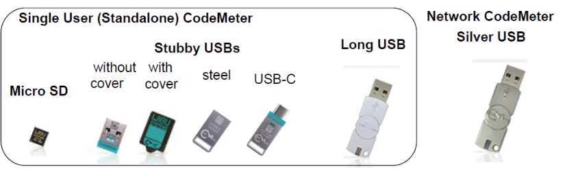
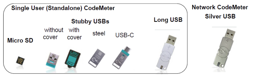
Upon purchasing a 12d Model licence or licences, you’ll usually receive: a standalone Codemeter or a network Codemeter dongle (or both).

Standalone dongles come in several forms such as an SSD card, a stubby USB, or a long USB drive. While they may look different, they all serve the same purpose. These are designed for individual users and allow access to multiple projects, with the option to be shared when needed.

For team environments, a network dongle is used instead. This is typically a heavier metallic USB device, where each licence allows one user to access a project at a time, making it suitable for shared organisational use.

By the end of this video, you’ll have a clear understanding of how each dongle type works and which one applies to your setup.

Watch the full video to get a simple, visual guide to 12d Model dongle types and licensing.

History Files: Sydney Olympic Arena Checks in with 12d Model

For the Millennium project at Sydney Olympic Park, contractor Graham Wirth and Abigroup (now Lendlease – https://www.lendlease.com/au/) leveraged advanced 12d Model technology to deliver precise on-site quality assurance for the construction of Australia’s largest indoor sports and entertainment arena in NSW, Australia.

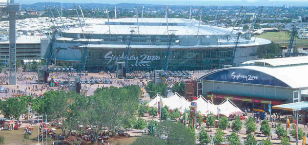
On-site quality assurance checking of all steps in the construction of Australia’s largest indoor sports and entertainment centre is being carried out through 4D Model (later renamed 12d Model).

Architectural and engineering service models are being fed on-site into a 4D survey model to ensure that construction of the Multi-Use Arena at Sydney Olympic Park, Homebush, goes exactly according to plan.

The Multi-Use Arena is being designed and built by construction giant Abigroup Contractors. As well as being a key venue for the Sydney 2000 Olympic Games and Paralympic Games, it is expected to meet Sydney’s sporting and entertainment needs well into the future. Abigroup will operate the facility for 30 years through its control of Millennium, the management company for the Arena.

The fully roofed Arena has a 48 x 75 metre event floor which is surrounded by five levels of seating which can accommodate up to 20,000 spectators. The performance space is free of columns, which provides an uninterrupted view from all seats. There is also a large rehearsal hall with retractable seating for 900. The Arena is adjacent to a 3,500 space car park, also being built by Abigroup, which will be shared by other facilities at Homebush Bay.

Abigroup’s Chief Surveyor, Graham Wirth, said the 4D Model software was rigorously tested in an on-site trial before the company committed to long-term purchase. “The software is being used for survey file management, calculations and storage of as-constructed information,” he said. “During the trial period we found 4D Model superior to other systems in terms of speed, file handling and ability to transfer data to and from other packages. It is now coping with a huge amount of data and performing admirably.” 

Drawings and 2D files are supplied to the on-site surveyors, who put the files into 4D Model and convert them to 3D. The data in these files is compared with on-site survey information models built in 4D Model so that there are no possible clashes in the siting of engineering services, such as storm water grease lines and telecom lines, and structure positions, such as piling.

On-site survey information is collected using the TPSETOUT survey software package which links directly into 4D Model. TP-SETOUT records field data and compares the measurements to design parameters for setout and QA (quality assurance) purposes, then the data is compiled in 4D Model for quantity computations, data storage and transfer, and design modifications.

“The data is put together in 4D Model in layers, which is an excellent feature for visualisation,” said Mr Wirth. “Another good feature is the ability to use very long file names to enhance file management. “We are currently checking ground slabs in 4D model and are using around 30 layers at the moment for all our data,” he said. “We expect that by the time construction is finished in August 1999 this will at least double.

“4D Model is proving an excellent tool for handling very large project models. Our models currently contain about 60,000 to 70,000 points and this should at least double,” he said. “We’re confident that 4D Model will successfully see us through to the end of the project.”

Download this Case Study as a PDF HERE